Method and system for detecting effect of lighting device

Inactive Publication Date: 2010-12-16
KONINKLIJKE PHILIPS ELECTRONICS NV
View PDF26 Cites 35 Cited by
  • Summary
  • Abstract
  • Description
  • Claims
  • Application Information

AI Technical Summary

Benefits of technology

[0022]Ideally the operate signal transmitted to the effects device comprises an on signal, and the method further comprises transmitting a further operate signal to the effects device, this further operate signal transmitted to the effects device comprising an off signal. In this way the effect device is turned on and off for the purposes of identifying the location of the effect produced by the device. This is especially appropriate if the system is cycling through the different devices in turn.
[0023]The operate signal need not be of the on/off variety, as it may be advisable in some situations to use a change in gradient of the actual operating intensity of a device, and it can be the case that different effect locations can be categorised for the same device, dependent on the actual operating configuration of that device.
[0024]For example, a device may have three possible function positions, off, low and high. This could be the case for any type of effects device. The method may therefore obtain location information of the effect generated for both the “low” and “high” configurations of that device. The method can further comprise transmitting a series of different operate signals from the control system to the effects device, operating the effects device according to the different operate signals, and in this way, calculating an intensity curve for the effects device.
[0025]Preferably, the method can further comprise measuring a delay between transmitting the operate signal from

Problems solved by technology

This can be difficult for a user, in the sense that the user has to know and understand the concept of the location model that is being used by the specific augmentation system that is providing the extra effects.
Currently, it is only possible to manually set the location of an effects device by, for instance, adjusting a location switch on the lighting device itself or changing the location setting in the device f

Method used


Image

  • Method and system for detecting effect of lighting device
  • Method and system for detecting effect of lighting device
  • Method and system for detecting effect of lighting device

Examples


Embodiment Construction

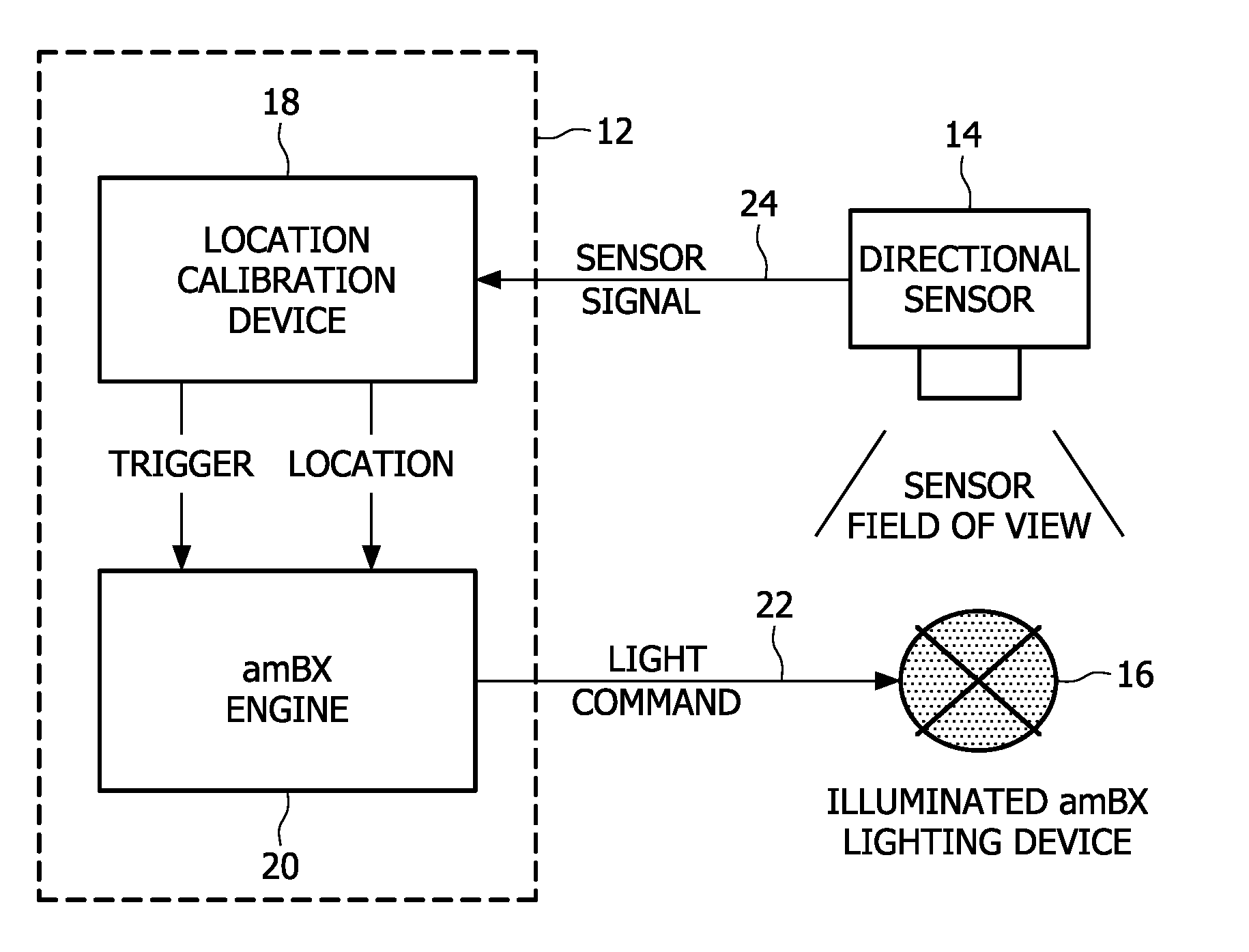
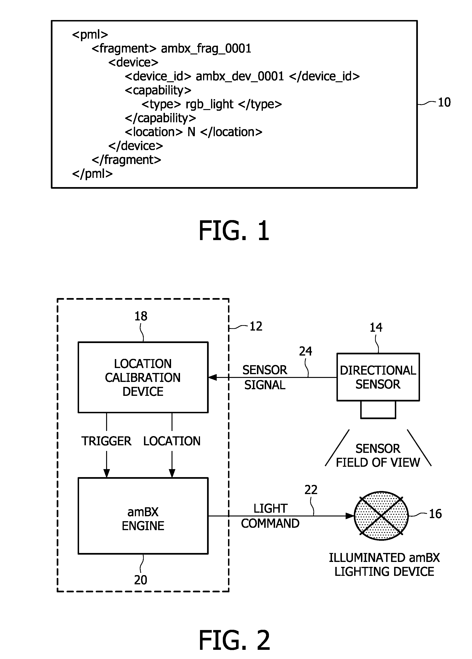
[0037]FIG. 2 shows a system which comprises a control system 12, a detecting device 14 and one or more effects devices 16. The effects device 16 is a lighting device 16. The control system 12 has two components, a location calibration unit 18 and an amBX engine 20. The configuration of the control system 12 can be a dedicated piece of hardware, or could be a distributed software application that is responsible for the control of the various effects devices 16.

[0038]One possible embodiment is for the detecting device 14 to comprise a small location calibration device with a sensor that is directionally sensitive, such as a (wide-angle) camera or directional light sensor. This sensor can be placed at the location where the user normally resides when he or she is using the overall augmentation system.

[0039]The control system 12 is arranged to transmit an operate signal 22 to the effects device 16. By means of a trigger from the location calibration device 18, which can be a software ap...


PUM


Abstract

A method comprises transmitting an operate signal from a control system to an effects device, operating the effects device according to the operate signal, detecting an effect of the effects device, assigning a location to said effect, and storing the location of said effect. The effects device can comprise a lighting device, and the method can be repeated for multiple effects devices.

Description

FIELD OF THE INVENTION[0001]This invention relates to a method of and system for detecting and locating the effect of an effects device, such as a lighting device. The invention provides the automatic location calibration for multiple effects devices, such as lighting devices, present in an ambient environment system.BACKGROUND OF THE INVENTION[0002]Developments in the entertainment world have led to the creation of augmentation systems, which provide additional effects in addition to a user's primary entertainment experience. An example of this would be a film, which is being presented by a display device and connected audio devices, and is augmented by other devices in the ambient environment. These additional devices may be, for example, lighting devices, or temperature devices etc. that are controlled in line with the film's content. If a scene is being shown in the film that is underwater, then additional lights may provide a blue ambient environment, and a fan may operate to l...

Claims


Application Information

Patent Timeline
IPC IPC(8): H05B37/00G06F17/00G10L15/00
CPCH04N21/4131H05B37/029H05B37/0245H04N21/44008H05B47/175H05B47/155
Inventor CUPPEN, ROEL P.G.BERKVENS, WINFRIED A.H.VERBERKT, MARK H.
Owner KONINKLIJKE PHILIPS ELECTRONICS NV
Why Eureka
Try Eureka