Outdoor unit for air conditioner

a technology for outdoor units and air conditioners, which is applied in the field of outdoor units for air conditioners, can solve the problems of affecting the design of the exterior appearance, affecting the efficiency of air conditioning equipment, and affecting the appearance of the exterior, and achieves the effect of preventing water droplets and simple structur

Active Publication Date: 2010-12-23
MITSUBISHI ELECTRIC CORP
View PDF33 Cites 39 Cited by
  • Summary
  • Abstract
  • Description
  • Claims
  • Application Information

AI Technical Summary

Benefits of technology

[0012]The present invention aims to prevent water droplets from flowing into a gap between a fan and a bell mouth with a simple structure, for example.

Problems solved by technology

However, there are following problems in preventing water droplets from flowing into the bell-mouth part by sealing the gap between the casing and the outlet grille as in the conventional way.
Farming the flange in the outlet grille impairs design of the exterior appearance.
Further, it is necessary to combine a plate-like member with the iron wire part in order to form the flange in the outlet grille, which results in higher manufacturing cost.
However, fixing the outlet grille only at its four corners to the casing with screws causes the outlet grille to wobble and vibrate, and makes it difficult to seal the clearance at the center part with a seal member.
An increase in the number of the screws impairs design of the exterior appearance and worsens work efficiency in production or the like.
For this reason, when the gap between the casing and the upper part of the outlet grille is sealed in addition to use of this method, it is necessary to make the shape of the seal member in a curve to fit the deflected outlet grille, in which case secure sealing is difficult.
This results in an increase in noise and deterioration of aerodynamic performance.
Thus, as described in Japanese Utility Model Publication No. 4-132336, when the outdoor unit for the air conditioner wherein the gap between the casing and the outlet grille is sealed and water droplets do not flow into the bell mouth part is realized, the outdoor unit needs to have a complicated structure so that design of the exterior appearance is impaired, the manufacturing cost increases, and workability is worsened.

Method used


Image

  • Outdoor unit for air conditioner
  • Outdoor unit for air conditioner
  • Outdoor unit for air conditioner

Examples


embodiment 1

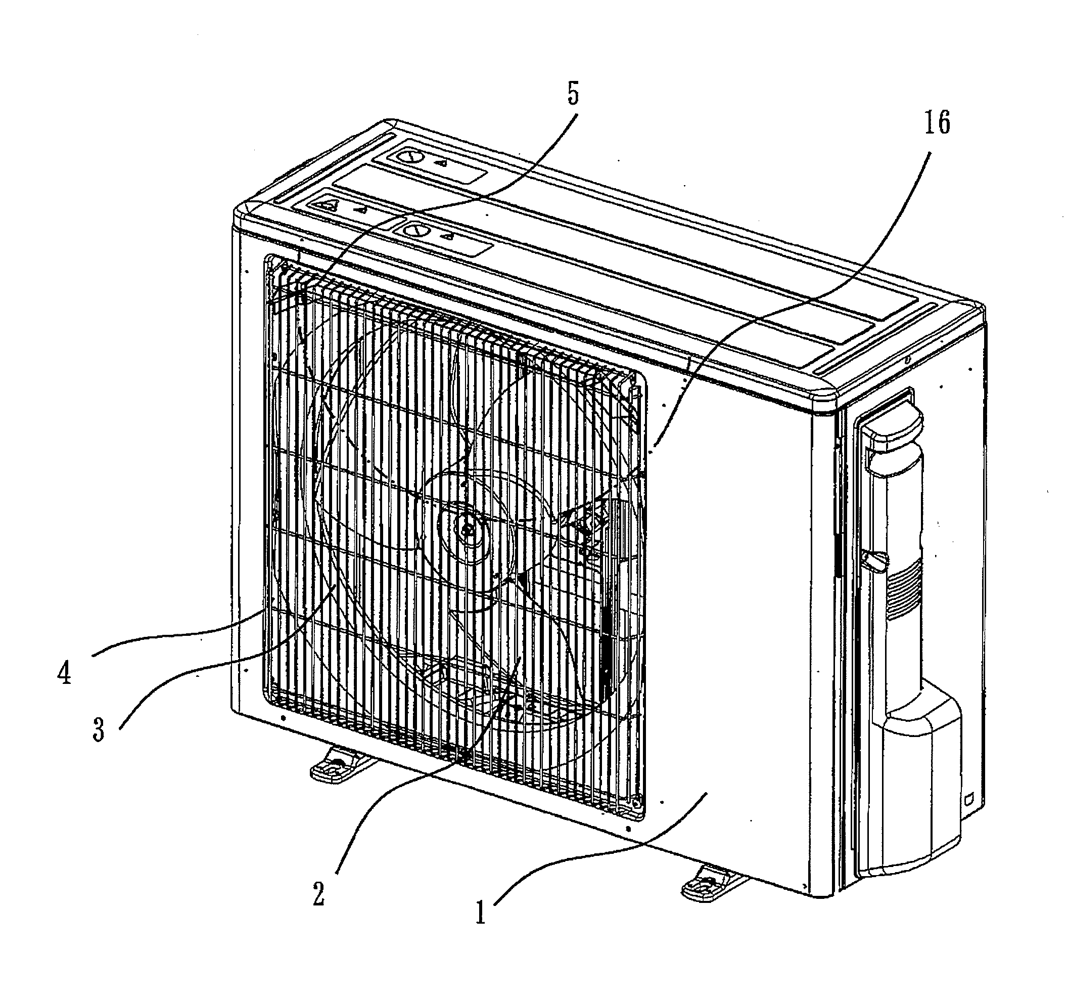
[0031]The outdoor unit for the air conditioner according to the first embodiment will be described based on FIG. 1 through FIG. 8.

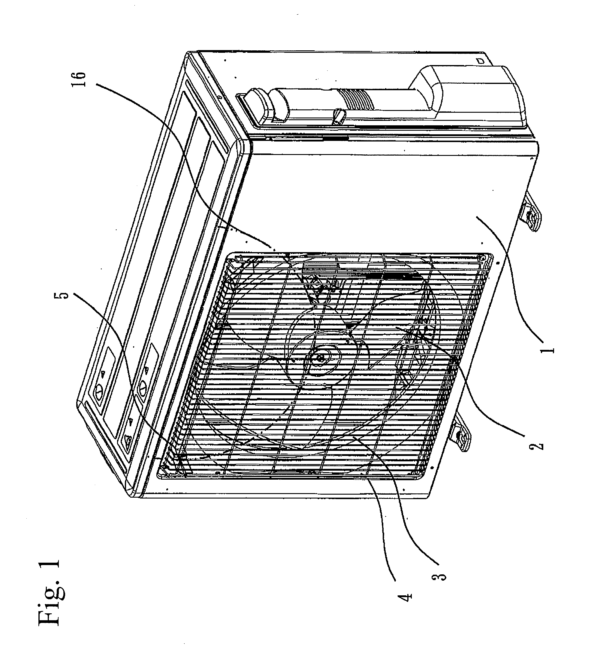
[0032]FIG. 1 is a perspective view of the outdoor unit for the air conditioner according to the first embodiment.

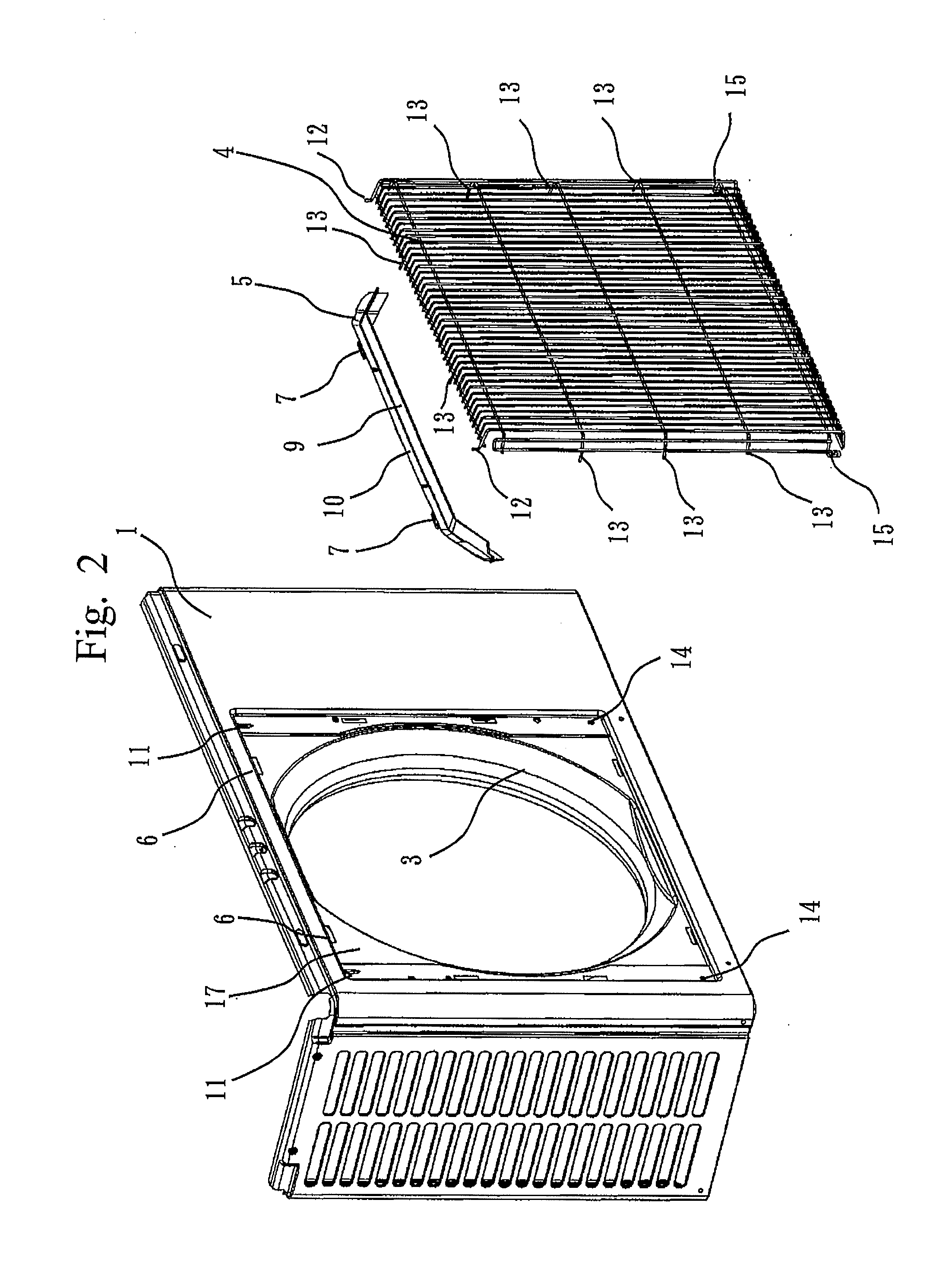
[0033]FIG. 2 through FIG. 4 are perspective views of the front surface part of the outdoor unit for the air conditioner according to the first embodiment. Particularly, FIG. 2 is a diagram illustrating the state where the front panel 1, the eaves member 5 and the outlet grille 4 are detached from one another. FIG. 3 is a diagram illustrating the state where the eaves member 5 is attached to and the outlet grille 4 is detached from the front panel 1. FIG. 4 is a diagram illustrating the state where the eaves member 5 and the outlet grille 4 are attached to the front panel 1.

[0034]FIG. 5 is a perspective view of the front surface part of the outdoor unit for the air conditioner according to the first embodiment, and is an enlarged view of the upp...

embodiment 2

[0064]An outdoor unit for an air conditioner according to the second embodiment will be explained based on FIG. 9 through FIG. 12. Particularly, only parts in the outdoor unit for the air conditioner according to the second embodiment different from those in the outdoor unit for the air conditioner according to the first embodiment will be explained.

[0065]FIG. 9 and FIG. 10 are perspective view of the front surface part of the outdoor unit for the air conditioner according to the second embodiment. Particularly, FIG. 9 is the diagram illustrating the state where the eaves member 5 is attached to and the outlet grille 4 is detached from the front panel 1. FIG. 10 is the diagram illustrating the state where the eaves member 5 and the outlet grille 4 are attached to the front panel 1.

[0066]FIG. 11 is the front perspective view of the eaves member 5 according to the second embodiment.

[0067]FIG. 12 is the back perspective view of the eaves member 5 according to the second embodiment.

[006...


PUM


Abstract

The present invention aims to prevent freezing of water droplets, etc. between a fan and a bell mouth. An outdoor unit for an air conditioner includes an eaves member that is placed above an air outlet formed by a bell mouth in close adherence with a front panel, and that protrudes toward a side of an outlet grille. Particularly, the eaves member is placed with a space from the outlet grille.

Description

BACKGROUND OF THE INVENTION[0001]1. Field of the Invention[0002]The present invention relates to an outdoor unit for an air conditioner that prevents freezing of water droplets, etc. between a fan and a bell mouth, for example.[0003]2. Background Art[0004]In an outdoor unit for an air conditioner, water droplets from rain, snow, etc., attached to a surface of a front panel of a casing, or water droplets formed from melted snow on top of the casing drop along the surface of the front panel to enter a gap between a bell mouth and a fan during a heating operation. When the outside air temperature is low, the temperature of blowout air from the fan can be equal to or below the freezing point. In this case, the water droplets entered the gap between the bell mouth and the fan freeze. Particularly, when the amount of water droplets is large, frozen ice can grow and contact with the fan to make extraordinary noise, or interrupt rotation of the fan to stop the outdoor unit abnormally.[0005]...

Claims


Application Information

Patent Timeline
Patent Type & Authority Applications(United States)
IPC IPC(8): F25D31/00F25D17/06
CPCF24F1/06F24F13/20F24F1/38
Inventor MOCHIZUKI, TATSUYAKUBONO, TOSHIYUKIYAMAUCHI, NORIOJINNAI, HIROYUKI
Owner MITSUBISHI ELECTRIC CORP
Why Eureka
Try Eureka