
Mask securing device

Inactive Publication Date: 2010-12-23
AVON POLYMER PROD LTD
View PDF9 Cites 23 Cited by
  • Summary
  • Abstract
  • Description
  • Claims
  • Application Information

AI Technical Summary

Benefits of technology

[0014]There are numerous disadvantages to such systems. Primary amongst these is that the mask arms may be unnecessary in certain situations. If, for example the user is not wearing the helmet, the mask is either unusable or, if used, interferes with the user's comfort due to movement of the unattached arms. So, the mask can only be used at times where the correct helmet is worn by the user, and when the particular mask is appropriate. This means that, for maximum safety of the users, a variety of masks must be provided for each circumstance. This is not only excessively costly, but may unduly burden the user with extra equipment, only some of which is ever in use. Additionally, the pressure keeping the mask to the user's face is transferred by the connecting arms at the edges of the mask, which leads to pressure being put on the body of the mask. Such lateral pressure can deform the mask and inhibit its function, or even compromise the integrity of the seal provided by the mask.

Problems solved by technology

There are numerous disadvantages to such systems.
Primary amongst these is that the mask arms may be unnecessary in certain situations.
If, for example the user is not wearing the helmet, the mask is either unusable or, if used, interferes with the user's comfort due to movement of the unattached arms.
This is not only excessively costly, but may unduly burden the user with extra equipment, only some of which is ever in use.
Additionally, the pressure keeping the mask to the user's face is transferred by the connecting arms at the edges of the mask, which leads to pressure being put on the body of the mask.
Such lateral pressure can deform the mask and inhibit its function, or even compromise the integrity of the seal provided by the mask.
Deformation of the mask is limited by both the spread of load across the mask and the pressure element itself, which reduces deflection of the mask material.

Method used


Image

  • Mask securing device
  • Mask securing device
  • Mask securing device

Examples


first embodiment

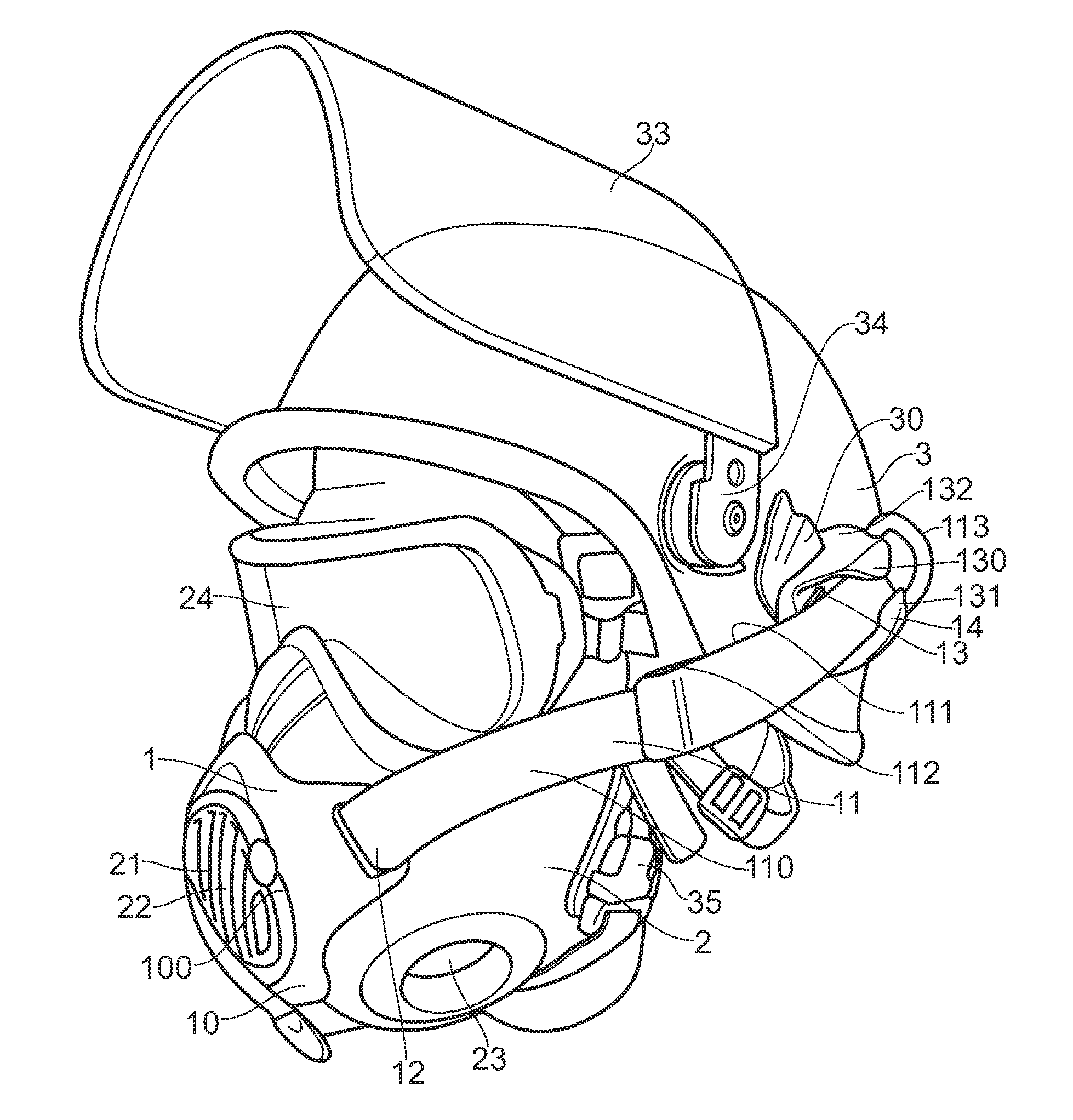
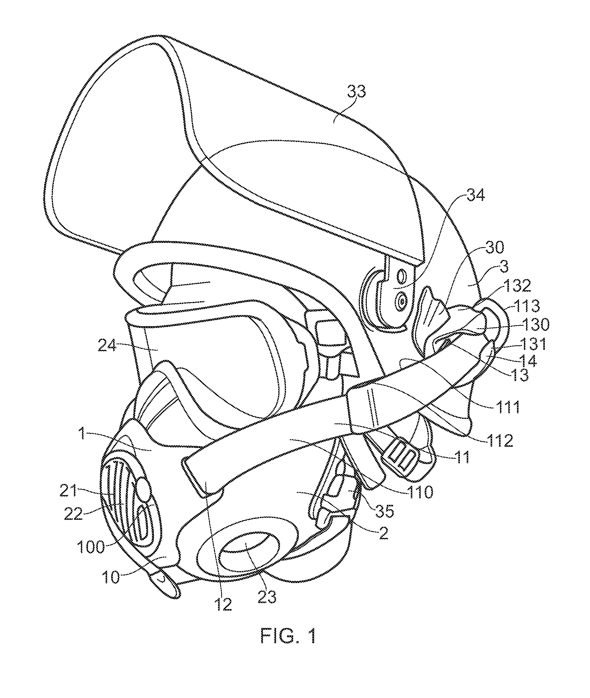
[0090]FIG. 1 shows the present invention. A bracing device 1 is shown fitted to a respirator mask 2 and attached to a helmet 3. The helmet 3 has a visor 33 mounted via hinges 34, and attachment slots 30 (one shown) therein. A series of straps 35 are provided for fine adjustment of the exact fit of the helmet 3. The respirator mask 2 comprises a front module 21, in which exhale valve 22 is formed. The mask covers the face of the user (not shown), to protect from dangerous environments. The mask has fitments 23 for filter modules, and a further protective visor portion 24 for protecting the eyes of the user. Of course, similar bracing devices can be used with other types of mask and headgear.

[0091]In the illustrated embodiment, the bracing device 1 comprises a pressure element 10, connection portions in the form of flexible straps 11, and helmet mounting portions 14. Note that, although only one strap 11 and helmet mounting portion 14 can be seen in FIG. 1, another pair is provided on...

second embodiment

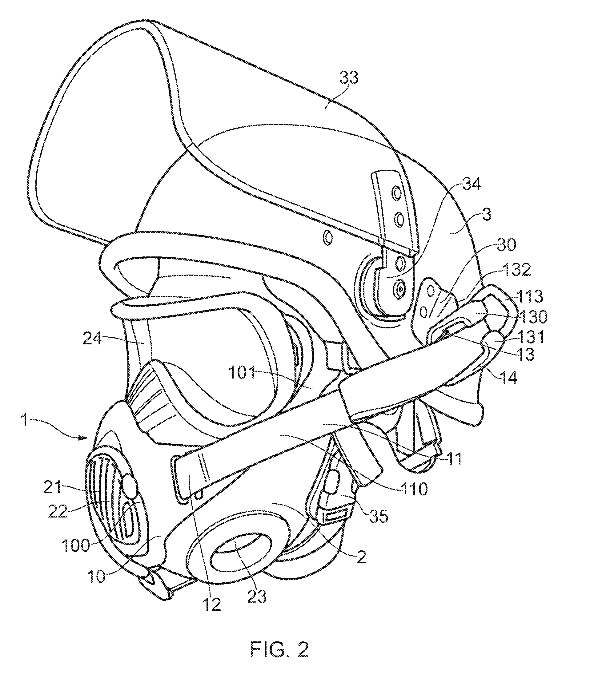
[0096]FIG. 2 shows the present invention. This embodiment is similar to that shown in FIG. 1, except in the shape of the pressure element 10. In this embodiment, the pressure element 10 further comprises arms 101 extending to a position proximal the user's orbital bone. The arms 101 engage the mask 2, providing further distribution of pressure and evening the pressure of the user's face.

[0097]FIG. 3 shows a close up of a helmet mounting portion 14 for use in the present invention. This figure more clearly shows the hook projection 132 for fixing the helmet mounting portion 14 to a suitably adapted headgear. The channel formed by the inwardly extending flanges 130, 131 can also be seen.

third embodiment

[0098]FIGS. 4 to 8 show a series of the steps involved in using the present invention to hold a mask to a user's face. The connection portions 11 of this embodiment are fitted with an elasticated expansion section 114, which allows for a more comfortable and flexible fit to the user's face. FIG. 4 shows the bracing device 1 fitted over the front module 21 of a mask 2, although the bracing device 1 and the mask 2 are separable.

[0099]When the bracing device 1 is firmly seated on the mask 2, for example by way of lugs 102 as shown in FIG. 9, the user positions the mask 2 on their face. This is shown in FIG. 5. The mask 2 fits onto the user as normal—with the illustrated arrangement, this means that the mask 2 fits partially under the helmet 3.

[0100]Once the mask 2 is in position, each of the helmet mounting portions 14 is attached to the helmet 3, as shown in FIG. 6, in the illustrated embodiment by way of fitting the hook projection 132 into the attachment slot 30 provided on the helm...


PUM


Abstract

A respirator assembly has a respirator mask and a separate bracing device. The bracing device has a pressure element mountable over a frontpiece of the respirator mask, which bears against that frontpiece to hold the respirator mask against the face of a user. The bracing device also has two connection portions, each having one end attached to the pressure element and the other end being for attaching the bracing device to a helmet worn by the user. The connection portions are extendable. Thus, shortening or distending the connection portions reduces the distance between the helmet and the respirator mask and thereby causes the pressure element to bear against the frontpiece of the respirator mask, compressing the user's head between the helmet and the mask and thereby holding the mask against the user's face.

Description

CROSS-REFERENCE TO RELATED APPLICATION[0001]This application claims the benefit of GB0910582.6, filed Jun. 19, 2009, which is incorporated herein by reference in its entirety.BACKGROUND OF THE INVENTION[0002]1. Field of the Invention[0003]This invention relates to a device for securing a mask to the face of a user, more particularly to a device for use where the user is wearing headgear.[0004]2. Summary of the Prior Art[0005]Many types of mask are known, including the respirator (or ‘gas’) mask. Such masks are primarily used in extreme situations, such as warzones, police operations and fires. They serve to protect the user from inhalation of harmful substances such as smoke or chemical and biological agents. So, it is vitally important that the mask can be donned quickly and easily by the user, to limit any possible exposure. Respirator masks employ filtration systems to purify air before it is inhaled by the user, and a tight seal between the mask and the face of the user is of gr...

Claims


Application Information

Patent Timeline
IPC IPC(8): A62B18/08
CPCA62B18/084A42B3/288
Inventor CONNELL, DAVID ANDREW
Owner AVON POLYMER PROD LTD
Learn More