
Printing apparatus and printing method

a printing apparatus and printing method technology, applied in the direction of printing, other printing apparatus, etc., can solve the problems of inability to impact print media, deviation of impact position of ejected ink droplets, and defective portions of print images that concentrate in particular areas of print images, so as to achieve the effect of reducing printing throughpu

Inactive Publication Date: 2010-12-23
CANON KK
View PDF2 Cites 13 Cited by
  • Summary
  • Abstract
  • Description
  • Claims
  • Application Information

AI Technical Summary

Benefits of technology

The present invention provides a printing apparatus and method that can prevent ejection failure and decrease in printing throughput while maintaining high-quality print images. This is achieved by sensing the ejection state of ink through different ejection ports in a print head and performing compensation printing using a different ejection port to form the same dot. The likelihood of ejection failure is determined and compensation printing is carried out accordingly, minimizing the time for which printing is suspended and reducing the impact on printing throughput.

Problems solved by technology

On the other hand, in the ink jet printing apparatus, inappropriate ink ejections may result from, for example, blockage of ejection ports by dust or thickened ink or coverage of ejection ports with ink droplets.
Such an inappropriate ink ejection may be an ejection failure state in which no ink droplets are ejected from ejection ports, a state in which ink droplets are ejected but in which an ejection speed is lower than a predetermined value, resulting in a failure to impact print media, or deviation of impact positions of ejected ink droplets.
When such an inappropriate ink ejection is occurred, particularly in an ink jet printing apparatus with a small number of passes, corresponding defective portions concentrate in particular areas of print images.
However, since the process of sensing is carried out individually on the respective ejection ports, particularly if the printing apparatus includes a large number of ejection ports like those configured to print large-sized print media as described above, printing needs to be halted for a long time.
Thus, when the sensing of the ejection failure state is excessively frequently carried out, the time for which printing is suspended for the sensing of the ejection failure state increases unnecessarily.
This may reduce printing throughput.
Furthermore, this new ejection failure state occurred much more frequently than those recognized in the conventional art.
Thus, when an attempt is made to compensate for the ejection failure state with the conventional design concept unchanged, achieving both high image quality and a high throughput is very difficult.

Method used


Image

  • Printing apparatus and printing method
  • Printing apparatus and printing method
  • Printing apparatus and printing method

Examples


first embodiment

[0030]An ink jet printing apparatus according to a first embodiment of the present invention will be described. The ink jet printing apparatus according to the present embodiment is assumed to be used to print relatively large-sized print media, for example, used for commercial applications such as printing of posters and POP advertisements and industrial applications. Thus, an ink jet printing apparatus configured to print roll paper will be described.

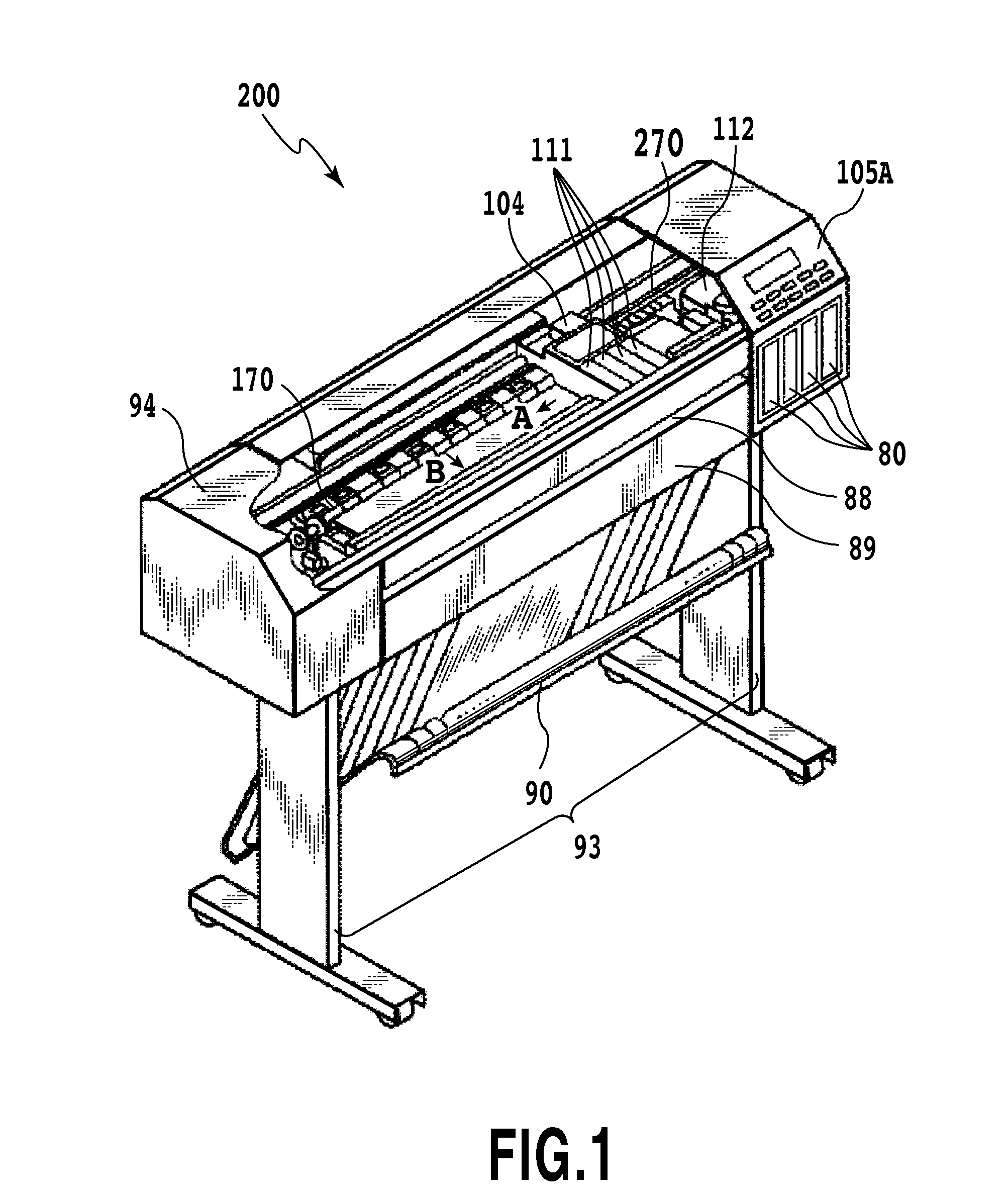
[0031]FIG. 1 is a perspective view of an ink jet printing apparatus (hereinafter also simply referred to as a printing apparatus) 200 which is partly exploded so as to show the internal structure. FIG. 1 shows the ink jet printing apparatus 200 with an upper cover removed therefrom.

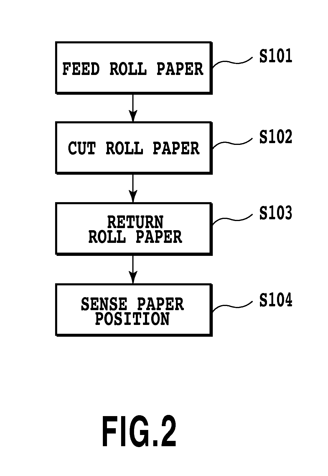
[0032]As shown in FIG. 1, a manual insertion port 88 is formed in the front surface of the printing apparatus 200. A roll paper cassette 89 that can be opened forward is provided under the manual insertion port 88 shown in FIG. 1. Cut paper with a fixed len...

second embodiment

[0099]Now, a second embodiment will be described with reference to FIG. 11. Components of the second embodiment which are configured similarly to the corresponding ones of the first embodiment are denoted by the same reference numerals and will not be described below. Only differences from the first embodiment will be described. FIG. 11 shows a plan view of an ejection port formation surface of a print head according to the second embodiment.

[0100]According to the above-described first embodiment, in the ejection ports in the print head 111 used in the printing apparatus, for each of the black ink and the yellow ink, one ejection port row is formed. For each of the cyan ink and the magenta ink, two ejection port rows are formed. Thus, the ejection port rows formed in the print head are not symmetric. Hence, while the print head 111 is scanning, the color impression may vary between the forward scanning direction and the backward scanning direction. Therefore, the print head 111 is n...

third embodiment

[0106]Now, an ink jet printing apparatus according to a third embodiment will be described. Components of the third embodiment which are configured similarly to the corresponding ones of the first or second embodiment are denoted by the same reference numerals and will not be described below. Only differences from the first and second embodiments will be described.

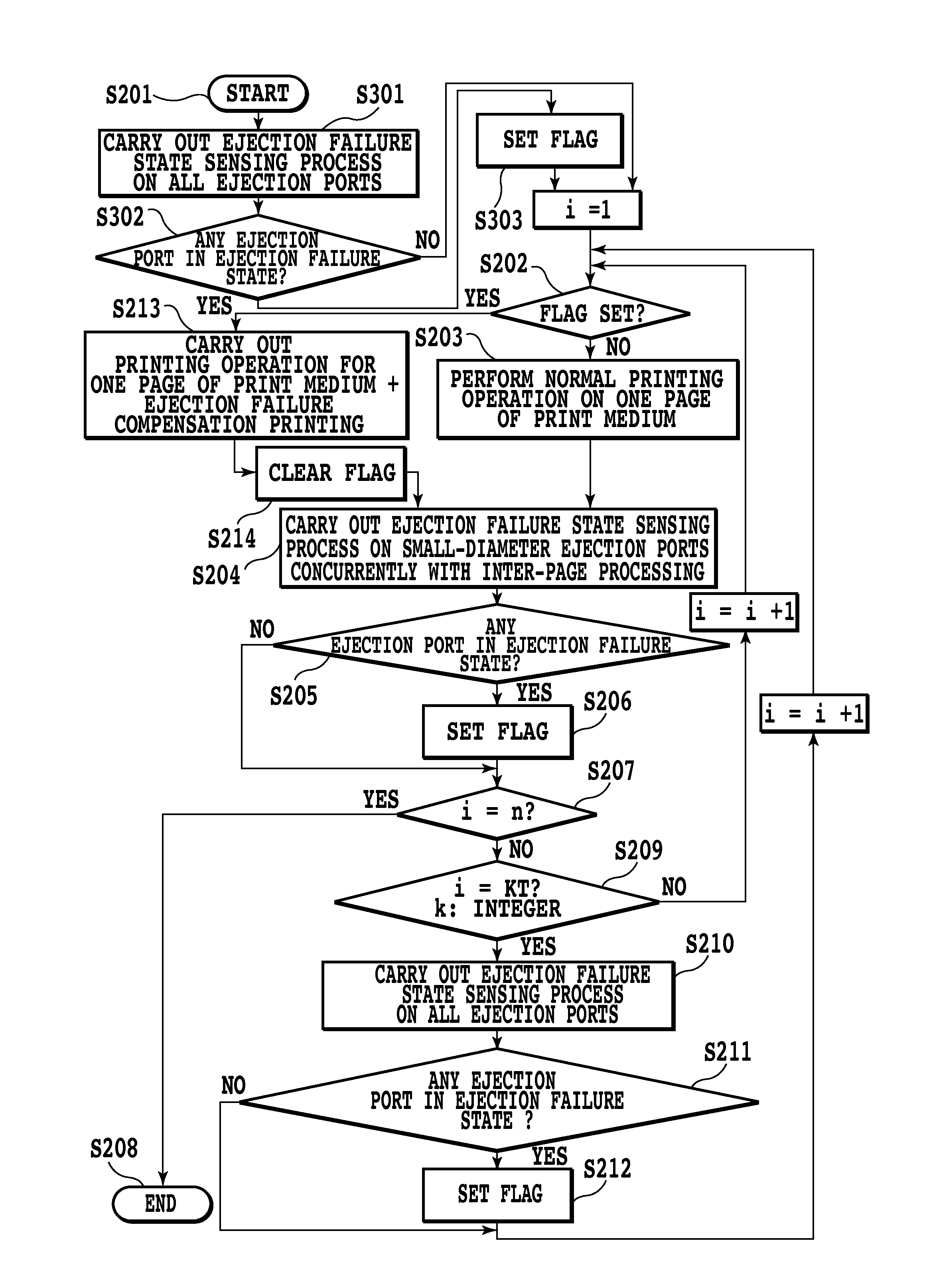
[0107]In the above-described first and second embodiments, when printing of each page is finished, the ejection failure state sensing process for the ejection ports is carried out concurrently with the inter-page processing. The time required for the ejection failure state sensing process for the ejection ports varies depending on conditions such as the number of ejection ports formed in the print head. The time required for the ejection failure state sensing process increases consistently with the number of ejection ports formed in the print head. If this amount of time exceeds the time required for the inter-page process...


PUM


Abstract

A printing apparatus and a printing method in which an ejection failure state sensing process is sufficiently carried out while a decrease in printing throughput to be suppressed are provided. The print head includes at least two ejection ports through which different amounts of ink in the same color are ejected; both ejection amounts are equal to or smaller than 5 pl. The printing apparatus carries out a first ejection failure state sensing process for sensing a first ejection ports which have the smallest opening area in the ejection ports formed in the print head. The printing apparatus also carries out a second ejection failure state sensing process for sensing an ejection state in which ink is ejected through all the ejection ports in the print head. When any ejection port is determined to be in an inappropriate ejection state, the printing apparatus carries out compensation printing.

Description

BACKGROUND OF THE INVENTION[0001]1. Field of the Invention[0002]The present invention relates to a printing apparatus and a printing method in which a print medium is printed by allowing a print head to eject ink, and in particular, to a printing apparatus and a printing method which involve sensing of the condition in which ink is ejected through ejection ports.[0003]2. Description of the Related Art[0004]In recent years, ink jet printing apparatuses have been prevailing rapidly printing is performed by allowing a print head to eject ink droplets to print medium. Many ink jet printing apparatus adopt an ink droplet ejection method in which ink is heated to cause film boiling so that the resulting pressure allows ink droplets to fly as an ink droplets ejection method. Unlike an electrophotographic scheme, this method requires no intermediate transfer unit and thus needs few intervening elements in forming images. Hence, the method has the advantage of allowing intended images to be ...

Claims


Application Information

Patent Timeline
Patent Type & Authority Applications(United States)
IPC IPC(8): B41J29/38
CPCB41J2/125B41J2/2139B41J29/393B41J29/38B41J2/2142B41J2/2125
Inventor MORI, TATSUYA
Owner CANON KK
Learn More