Wireless communication apparatus and wireless communication method

a wireless communication and wireless communication technology, applied in the direction of transmission monitoring, frequency-division multiplex, receiver monitoring, etc., can solve the problems of csi-rs transmission significantly adversely affecting an lte user equipment compatible only with an existing system, degradation of demodulation performance in the user equipment, and change in csi due to time-dependent fading, so as to prevent degradation of throughput

Active Publication Date: 2012-03-29
SUN PATENT TRUST
View PDF5 Cites 106 Cited by
  • Summary
  • Abstract
  • Description
  • Claims
  • Application Information

AI Technical Summary

Benefits of technology

[0037]According to the invention, it is possible to provide a wireless communication apparatus and a wireless communication method capable of suppressing concentration of channel quality information requests and reports in a case of discontinuously transmitting reference signals at specific resources in a time domain, and thereby preventing degradation in throughput.

Problems solved by technology

CSI-RS transmission significantly adversely affects an LTE user equipment compatible only with an existing system.
If such a rule is not provided, a signal which cannot be recognized from the LTE user equipment on the LTE user equipment-allocated resource is multiplexed, causing degradation of demodulation performance in the user equipment.
However, in a wireless propagation environment, as the time elapses, the change in CSI increases due to time-dependent fading.

Method used


Image

  • Wireless communication apparatus and wireless communication method
  • Wireless communication apparatus and wireless communication method
  • Wireless communication apparatus and wireless communication method

Examples


first embodiment

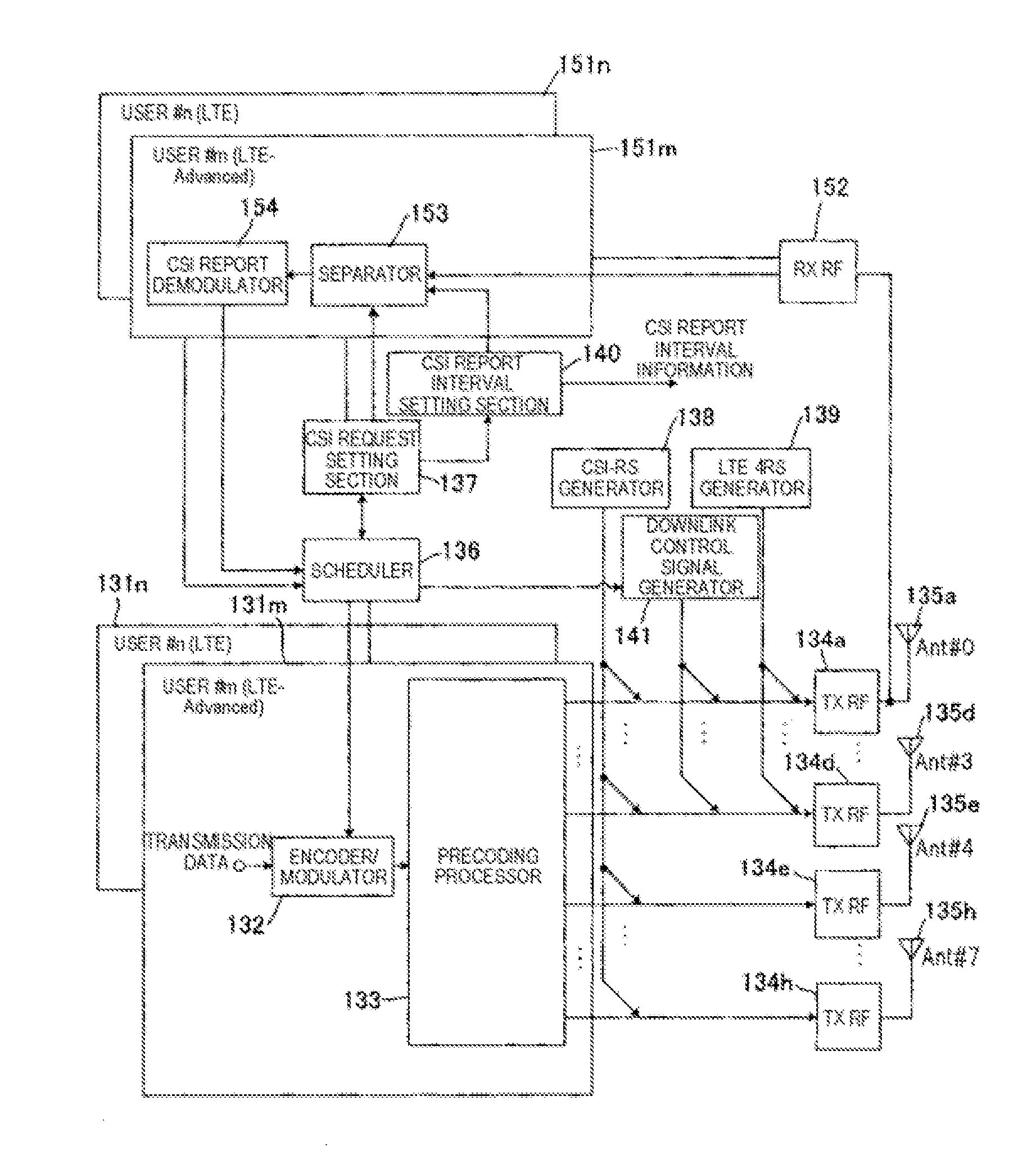
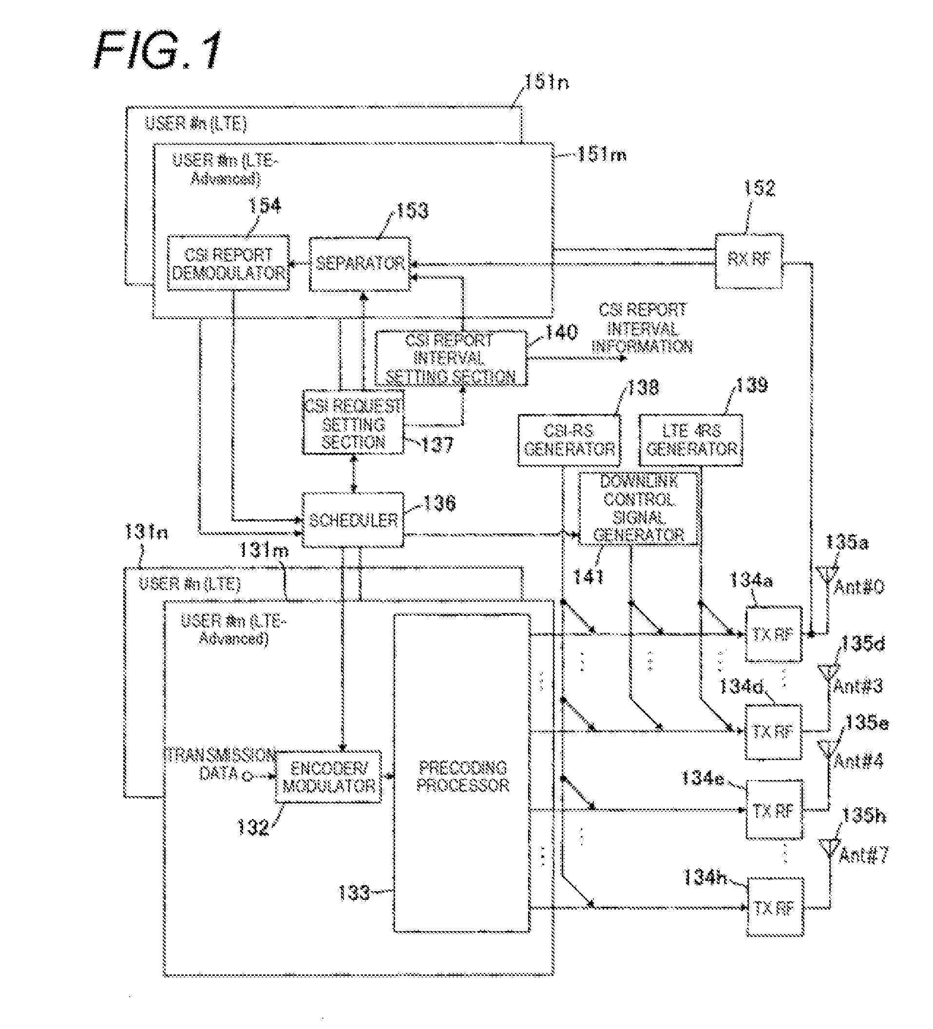
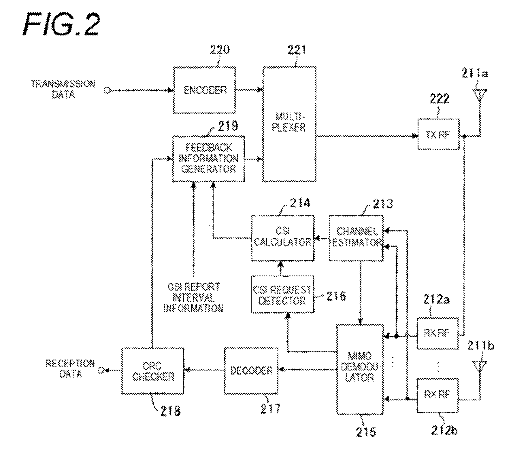
[0071]In a first embodiment, a CSI request as a channel quality information request is transmitted from a transmission apparatus to each reception apparatus to be temporally distributed over a plurality of reception apparatuses at the timing simultaneously with or earlier than the transmission timing of a reference signal CSI-RS for measuring CSI. The CSI request is a request which causes a CSI report value as a channel quality information report to be fed back from a reception apparatus serving as a communication party. Each reception apparatus calculates CSI from the reference signal CSI-RS, and transmits the CSI report from the reception apparatus to the transmission apparatus at the timing when a CSI report interval which is a given time interval set in advance elapses from the reception timing of the CSI request. The set value of the CSI report interval is a given subframe interval, and set in accordance with, for example, the number of reception apparatuses which perform commu...

second embodiment

[0100]In a second embodiment, the given CSI report interval set value in the first embodiment is set to be matched with a retransmission interval at the time of communication between a transmission apparatus and a reception apparatus in a wireless communication system. The transmission apparatus transmits a CSI request to each reception apparatus to be temporally distributed simultaneously with or earlier than the transmission timing of the reference signal CSI-RS for CSI measurement. Each reception apparatus calculates CSI from the reference signal CSI-RS, and transmits a CSI report to the transmission apparatus at the timing when the CSI report interval set value elapses from the reception timing of the CSI request, that is, when the retransmission interval elapses after the CSI request is received. Thus, the timing at which the CSI request is transmitted and the timing at which the CSI report is transmitted respectively are distributed.

[0101]FIG. 4 is a block diagram showing the ...

third embodiment

[0106]In a third embodiment, a CSI request is transmitted from a transmission apparatus to each reception apparatus to be temporally distributed at the timing earlier than the transmission timing of the reference signal CSI-RS for CSI measurement. In this case, as a value indicating how many subframes a CSI request is transmitted to each reception apparatus earlier than CSI-RS, a CSI report offset is set to differ among the reception apparatuses. Each reception apparatus sets the timing delayed by the CSI report offset after a predefined report interval elapses from the reception timing of CSI-RS as the CSI report timing of the own apparatus on the basis of the CSI report offset. Each reception apparatus calculates CSI from the reference signal CSI-RS, and transmits the CSI report to the transmission apparatus at the CSI report timing of the own apparatus. The CSI report offset can be acquired from the difference between the reception timing of the CSI request and the reception timi...


PUM


Abstract

To suppress concentration of channel quality information requests and reports in a case of discontinuously transmitting reference signals at specific resources in a time domain, and thereby preventing degradation in throughput. A transmission apparatus (eNB) transmits an instruction of CSI request distributed for each reception apparatus in a subframe concurrently with or earlier than a reference signal CSI-RS to each of reception apparatuses (UE1, UE2). Each of the reception apparatuses (UE1, UE2) detects the CSI request from the transmission apparatus and calculates CSI from a channel estimation value of CSI-RS received thereafter. Then, the reception apparatus identifies CSI report subframe of the own apparatus from CSI report interval information of a given time interval notified in advance, the subframe in which the CSI request is detected and transmission timing of CSI-RS, and transmits a feedback signal including CSI report value by using PUSCH at the timing of the CSI report subframe.

Description

TECHNICAL FIELD[0001]The present invention relates to a wireless communication apparatus and a wireless communication method which can be applied to a wireless communication system, such as a cellular system.BACKGROUND ART[0002]In a wireless communication system, such as a cellular system, a reference signal is introduced to obtain various indexes of a propagation channel and a transmission signal. For example, LTE (Long Term Evolution) of a next-generation communication system which is studied in the 3GPP (3rd Generation Partnership Project) as the international standards organization of mobile communication uses a reference signal (RS). In downlink communication from a base station to a user equipment, a reference signal which is transmitted from a transmission apparatus (base station) to a reception apparatus (user equipment) is mainly used for (1) estimation of a propagation channel for demodulation, (2) quality measurement for frequency scheduling and adaptive MCS (Modulation a...

Claims


Application Information

Patent Timeline
Patent Type & Authority Applications(United States)
IPC IPC(8): H04W24/10
CPCH04W24/10H04W72/1268H04B17/0085H04L1/0003H04B17/24H04L1/0027H04L1/1607H04L5/0048H04L1/0009H04B7/0626H04W72/0446H04W72/04H04W88/02
Inventor HOSHINO, MASAYUKINISHIO, AKIHIKONAKAO, SEIGOIMAMURA, DAICHIYUDA, YASUAKI
Owner SUN PATENT TRUST
Why Eureka
Try Eureka