
Carrier configuration method for multi-carrier communication system

a communication system and carrier configuration technology, applied in wireless communication, wireless communication, transmission path division, etc., can solve the problems of consuming relatively more radio resources and/or relatively more power to transmit cc configuration messages, and the configuration method is lack of flexibility, so as to reduce the size and amount of cc configuration messages transmitted between the bs and the terminal

Active Publication Date: 2010-12-23
IND TECH RES INST
View PDF11 Cites 31 Cited by
  • Summary
  • Abstract
  • Description
  • Claims
  • Application Information

AI Technical Summary

Benefits of technology

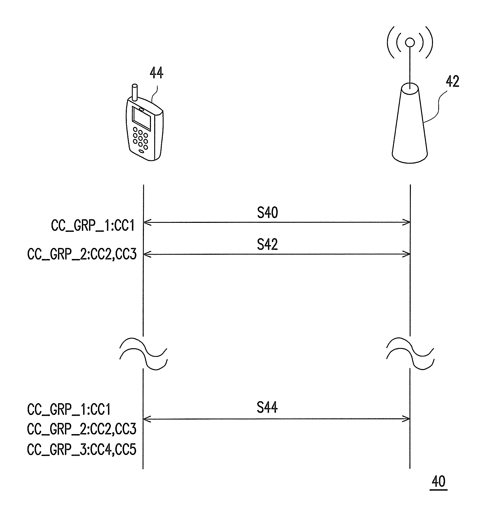
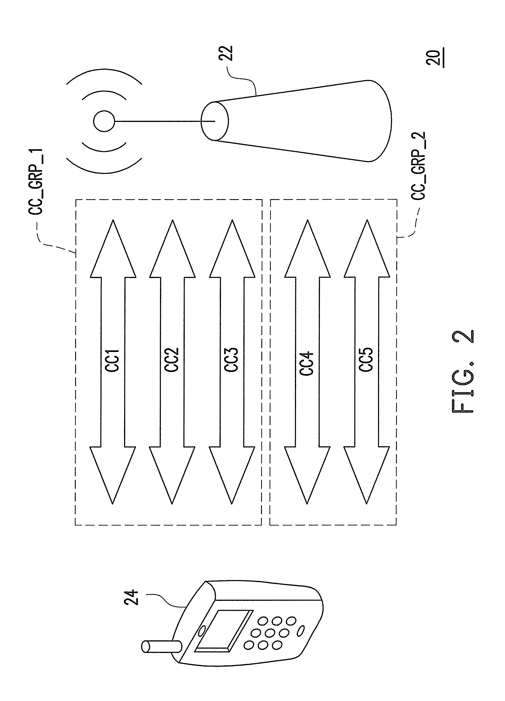
[0015]According to the above descriptions, in the carrier configuration method of the disclosure, the CCs using at least one identical configuration parameter are divided into the same CC group, and the BS can transmit the CC configuration message to the terminal, so that the terminal can set the configuration parameters of each CC in the CC group while taking the CC group as a unit. In this way, a size and amount of the CC configuration message transmitted between the BS and the terminal can be reduced. Moreover, an exemplary embodiment of the disclosure further provides a carrier configuration method based on an anchor carrier having a resource allocation message, by which the terminal can wake up the CC of the data to be received according to the resource allocation message. In this way, an additional notification message may be not needed. Besides, the above carrier configuration methods can also be applied to a 3GPP system, for example, UMTS, LTE or LTE-A, etc.

Problems solved by technology

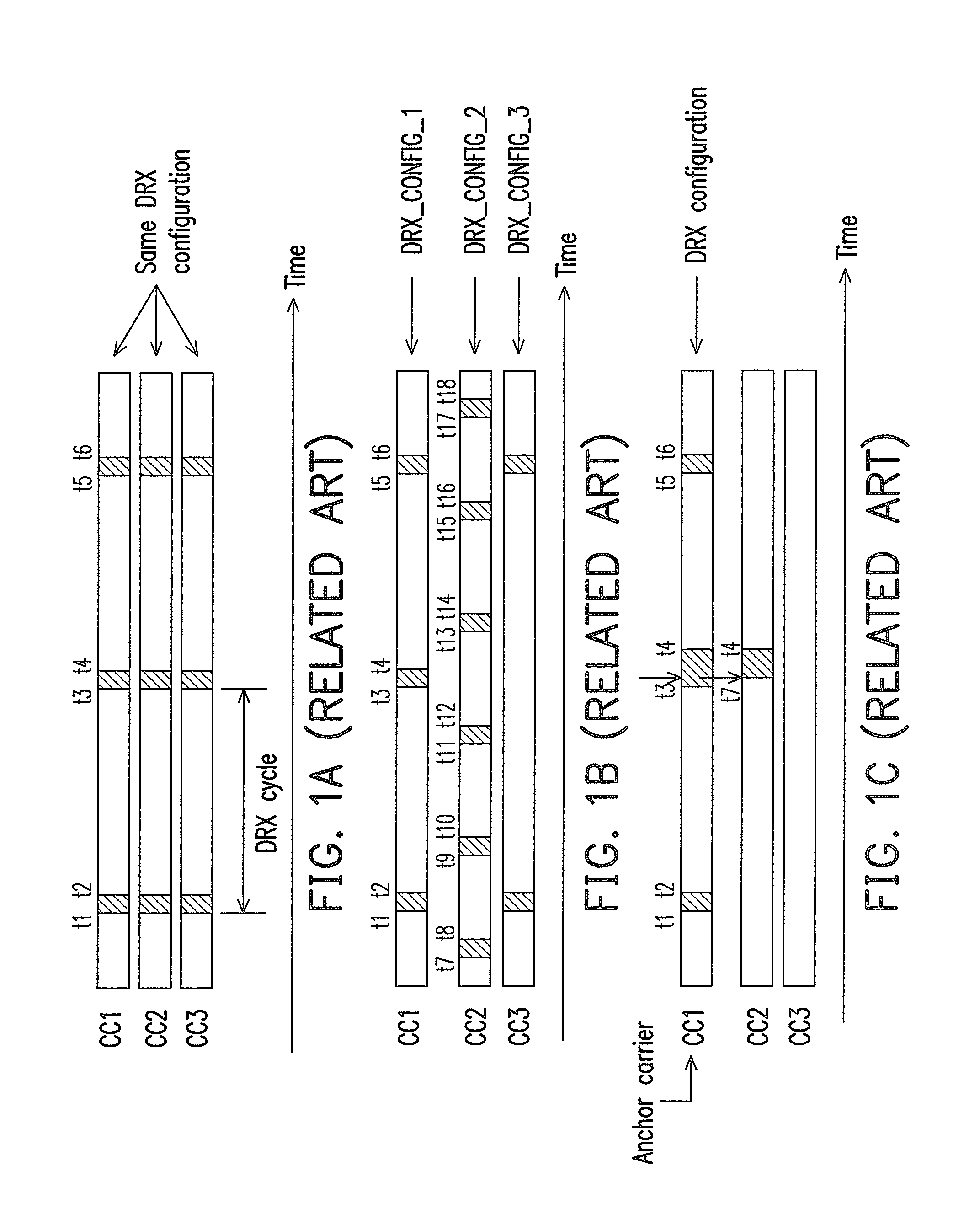
However, since all of the CCs have the same configuration, such configuration method is lack of flexibility.
In other words, the identical configuration method may lead to relatively more power consumption of the terminal.
Therefore, such configuration method may consume relatively more radio resources and / or relatively more power to transmit these CC configuration messages.

Method used


Image

  • Carrier configuration method for multi-carrier communication system
  • Carrier configuration method for multi-carrier communication system
  • Carrier configuration method for multi-carrier communication system

Examples


Embodiment Construction

[0034]Each conventional carrier configuration method has its advantages and shortages. To reduce a size of a component carrier (CC) configuration message transmitted between a base station (BS) and a terminal, and achieve flexibility of the carrier configuration method, an exemplary embodiment of the disclosure provides a carrier configuration method, by which the CCs using an identical configuration are divided into a same CC group, and the BS sets the configuration of the CCs while taking the CC group as a unit. Moreover, an exemplary embodiment of the disclosure further provides a carrier configuration method based on an anchor carrier having a resource allocation message, which can be applied for discontinuous reception (DRX) or semi-persistent scheduling (SPS). In this way, according to the carrier configuration methods provided by the exemplary embodiments of the disclosure, extra transmission and processing of radio resource control messages can be reduced.

[0035]Referring to ...


PUM


Abstract

A carrier configuration method for a multi-carrier communication system having a base station (BS) and a terminal is described. The BS divides multiple component carriers (CCs) of the terminal to multiple CC groups, wherein the CCs using at least one identical configuration parameter are divided into the same CC group. The BS transmits a CC configuration message comprising at least one configuration parameter data to the terminal, wherein the configuration message comprises or does not comprise at least one CC configuration indicator. If the configuration message comprises the CC configuration indicator, the terminal will receive the CC configuration message, and configure the configuration parameter of the configurations of the CCs indicated by the CC configuration indicator according to the configuration parameter data; otherwise, the terminal will configure the configuration parameter of the configurations of the default CCs (e.g. all of the CCs currently used by the terminal, or primary CCs).

Description

CROSS-REFERENCE TO RELATED APPLICATION[0001]This application claims priority benefits of U.S. Patent Provisional Application No. 61 / 218,218, filed on Jun. 18, 2009. The entirety of the above-mentioned patent applications is hereby incorporated by reference herein and made a part of this specification.BACKGROUND[0002]1. Field of the Disclosure[0003]The disclosure relates to a multi-carrier communication system. More particularly, the disclosure relates to a carrier configuration method for a multi-carrier communication system.[0004]2. Description of Related Art[0005]A multi-carrier terminal may transmit and / or receive a plurality of packets through one or a plurality of component carriers (CCs). To control the CCs to achieve different functions, a base station (BS) may set a specific configuration of the CCs of each terminal. For example, the BS may set a configuration of the CCs of the terminal to achieve discontinuous reception (DRX) or semi-persistent scheduling (SPS), wherein the...

Claims


Application Information

Patent Timeline
IPC IPC(8): H04W72/04H04L27/28
CPCH04L5/0007H04L5/001H04W72/0453H04L5/0094H04W72/042H04L5/0044H04W72/23
Inventor CHEN, CHUN-CHIA
Owner IND TECH RES INST
Learn More