Versatile collection apparatus for front loading refuse vehicle

a collection apparatus and refuse technology, applied in the field of refuse collection vehicles, can solve the problems of physical demanding and time-consuming time-consuming and inefficient manual loading of an intermediate container, and the range of motion of conventional collection assemblies is extremely limited

Active Publication Date: 2010-12-23
KANN MFG
View PDF13 Cites 32 Cited by
  • Summary
  • Abstract
  • Description
  • Claims
  • Application Information

AI Technical Summary

Benefits of technology

[0012]It is an object of the invention to provide a versatile collection apparatus for a front loading refuse vehicle which allows an operator in the cab of the vehicle to move an articulated grasping arm to grip a refuse receptacle located forward of or on the curbside or the streetside of the vehicle, including from cul-de-sac locations.
[0013]It is a further object of the invention to provide a collection assembly which may reach out from the refuse collection vehicle to grasp a refuse receptacle near the vehicle and empty the refuse receptacle into an intermediate container carried on the collection vehicle without an operator needing to depart the cab of the vehicle.

Problems solved by technology

As a result, manual loading of an intermediate container is physically demanding and time consuming.
Furthermore, manual loading of the intermediate container requires an operator to continuously board and depart the cab of the refuse collection vehicle at each individual collection site.
Consequently, manual loading of the intermediate container is time consuming and inefficient.
Because conventional collection assemblies can only extend in a single horizontal direction with respect to the intermediate container, conventional collection assemblies have an extremely limited range of motion.
In addition, conventional collection assemblies are incapable of collecting receptacles positioned on multiple sides of the intermediate container and are specifically configured for use only with a correspondingly configured refuse receptacle.
Consequently, conventional automated collection assemblies are inflexible as to both the positioning and the particular type of receptacle being used.

Method used


Image

  • Versatile collection apparatus for front loading refuse vehicle
  • Versatile collection apparatus for front loading refuse vehicle
  • Versatile collection apparatus for front loading refuse vehicle

Examples


Embodiment Construction

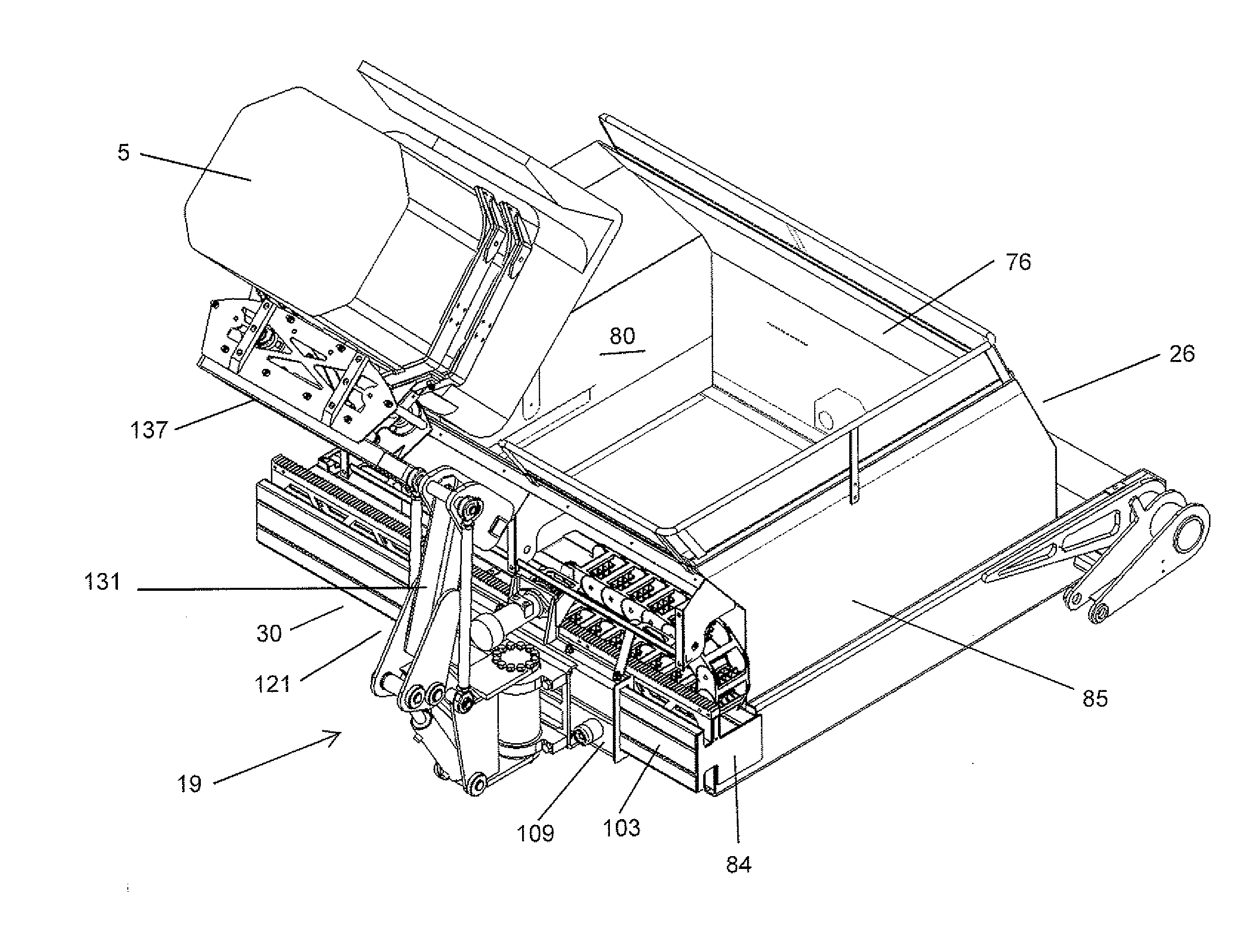
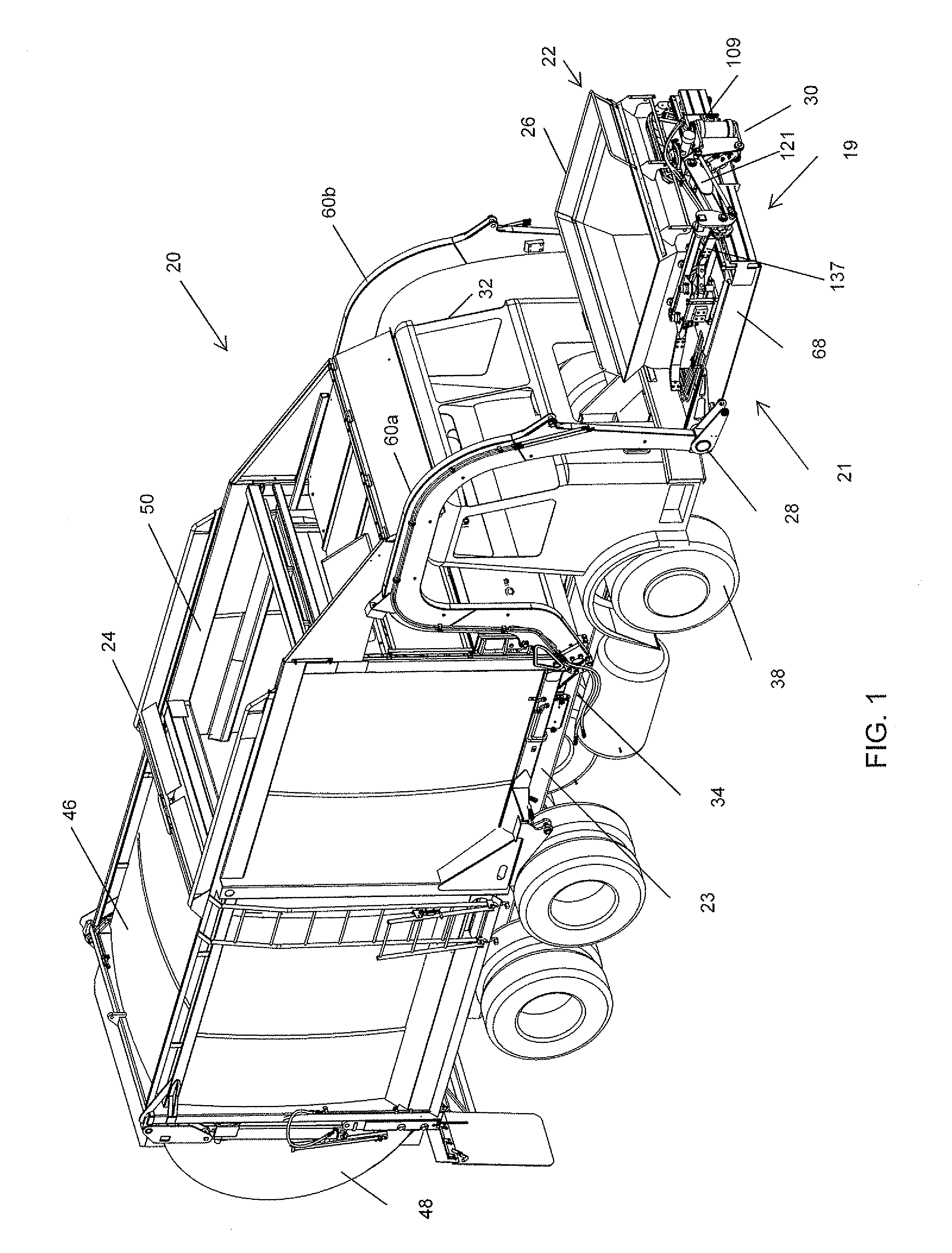
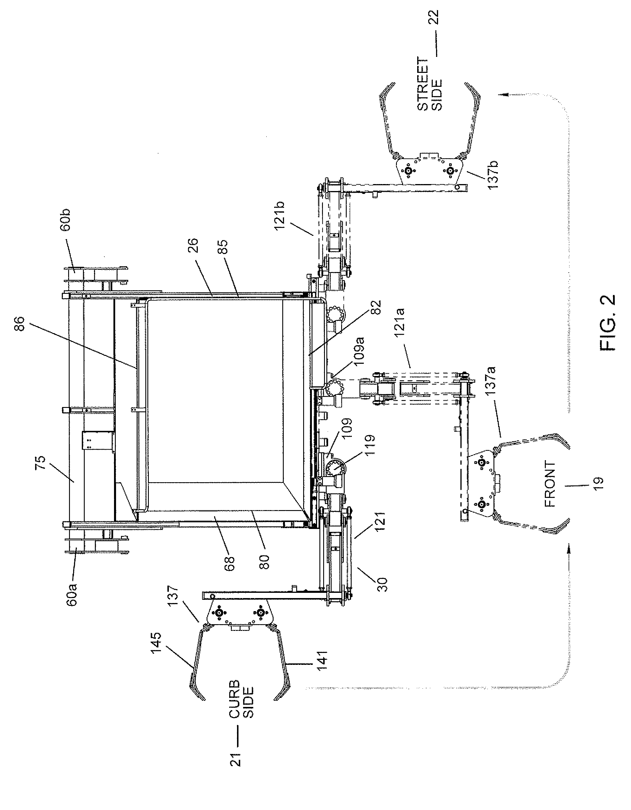
[0030]FIG. 1 is a perspective view of refuse collection vehicle 20 having a curbside 21, a street side 22 and a front side 19. Refuse collection vehicle 20 generally includes chassis 23, storage body 24, intermediate container 26, dumping assembly 28 and automated refuse receptacle collection assembly 30. Chassis 23 may have a variety of configurations depending upon the configurations of storage body 24. Chassis 23 supports and transports storage body 24, intermediate container 26 and dumping assembly 28 between material collection and disposal sites. Chassis 23 further includes cab 32, and wheels 38. Cab 32 is positioned forward of storage body 24 and rearward of intermediate container 26 and refuse receptacle collection assembly 30. Storage body 24 is mounted to and supported by frame 34 and includes storage portion 46, tailgate assembly 48 and intake compartment 50. Storage portion 46 extends between intake compartment 50 and tailgate assembly 48.

[0031]Upon release and opening o...


PUM


Abstract

A refuse collection assembly for a refuse collection vehicle mounts to a intermediate container on the refuse collection vehicle. The refuse receptacle collection assembly can grasp a refuse receptacle at curbside, at street side, or forward of the intermediate container in any location over a one hundred eighty degree arc. The collection assembly grasps the receptacle and locates it above the intermediate container and tilts it sufficiently to empty the contents of the receptacle in the intermediate container. The collection assembly then returns the receptacle upright to its previous location or to any location to the right, left or forward of the refuse collection assembly. The refuse receptacle collection assembly includes a rail extending along a wall of the intermediate container, a carriage selectively movable along the rail, and a receptacle engaging assembly supported by the carriage for grasping the refuse receptacle.

Description

CROSS-REFERENCE TO RELATED APPLICATIONS[0001]This application claims priority from copending provisional patent application entitled “Versatile Collection Apparatus for Front Loading Refuse Vehicle”, Ser. No. 61 / 218,488 filed Jun. 19, 2009. The disclosure of provisional patent application Ser. No. 61 / 218,488 is hereby incorporated in its entirety.BACKGROUND OF THE INVENTION[0002]The present invention relates to refuse collection vehicles for hauling waste and recyclable commodities. In particular, the present invention relates to a refuse collection vehicle having a storage body, an intermediate container for being unloaded into the storage body and an automated refuse receptacle collection assembly for engaging a refuse receptacle and unloading contents of the refuse receptacle into the intermediate container.[0003]Residential refuse is typically contained in relatively small receptacles or containers such as cans or carts which are positioned along the street for pick-up by a refu...

Claims


Application Information

Patent Timeline
Patent Type & Authority Applications(United States)
IPC IPC(8): B65F3/04B65F3/02
CPCB65F3/041B65F2003/023B65F2003/0279B65F2003/0269B65F2003/0273B65F2003/0266
Inventor ROWLAND, JARED L.JOHNSON, MARLIN L.GOEDKEN, KENNETH D.TAAKE, ROGER
Owner KANN MFG
Why Eureka
Try Eureka