Cylinder lock

a technology of cylinder locks and cylinders, applied in the field of cylinder locks, can solve the problems of reducing overall security, time-consuming and expensive process, and difficulty in repairing the door body, and achieve the effect of improving the anti-picking performan

Inactive Publication Date: 2010-12-30
CHUNG SHU LING
View PDF11 Cites 35 Cited by
  • Summary
  • Abstract
  • Description
  • Claims
  • Application Information

AI Technical Summary

Benefits of technology

[0008]It is therefore one object of the invention to provide a cylinder lock having an improved anti-picking performance.

Problems solved by technology

The disadvantage of this patent is that in order to install the device, a large section of the door interior volume needs to be removed, which is a difficult, time consuming and expensive process.
In addition, the door structure itself is substantially weakened, reducing overall security.
The lock is made of thin sheet metal and is not strong enough.
Further, conventional cylinder locks are inclined to be picked by unauthorized persons by inserting a metal wire, tweezers, or the like into the key hole by rotating the cylinder lock core.

Method used


Image

  • Cylinder lock
  • Cylinder lock
  • Cylinder lock

Examples


Embodiment Construction

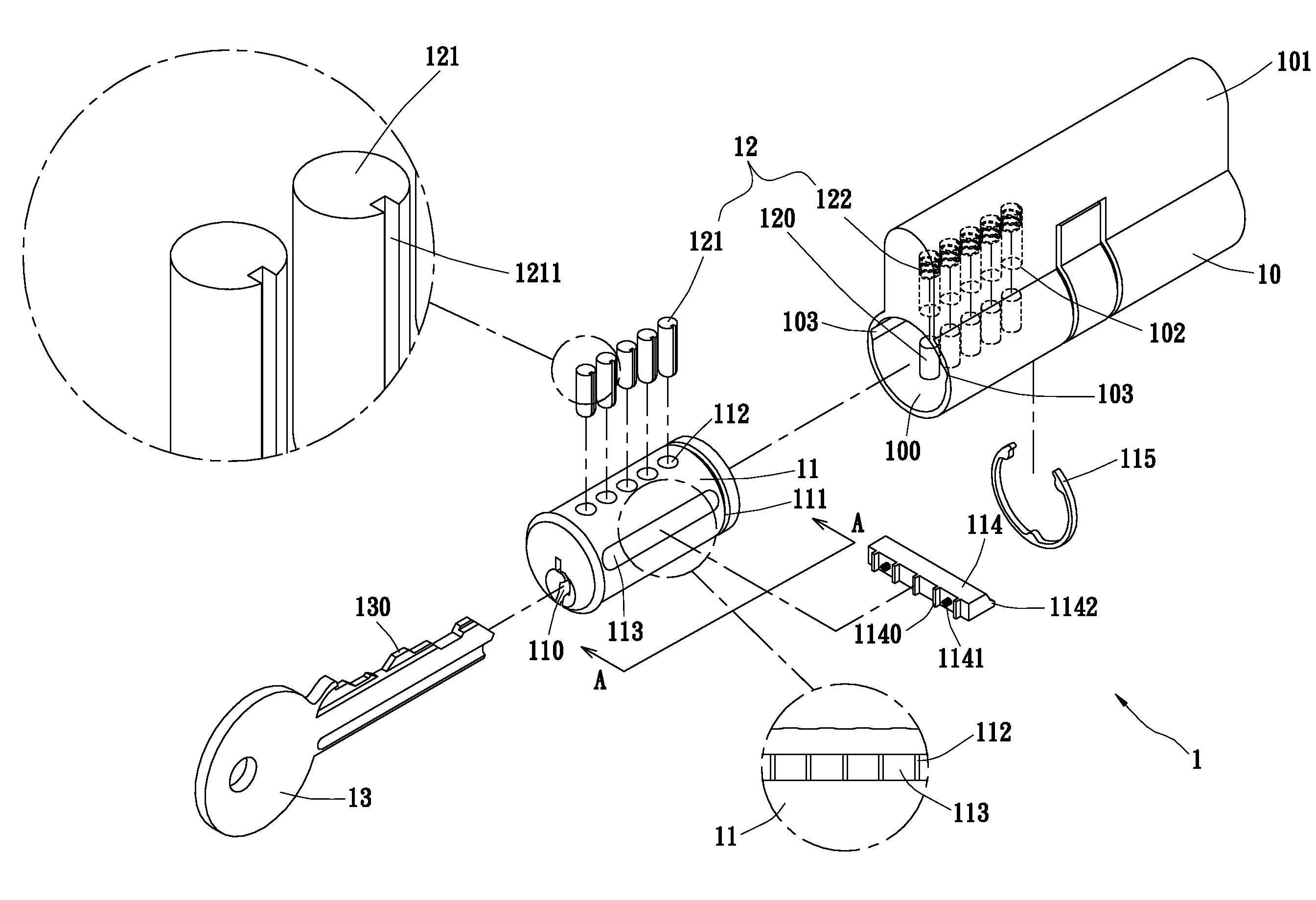
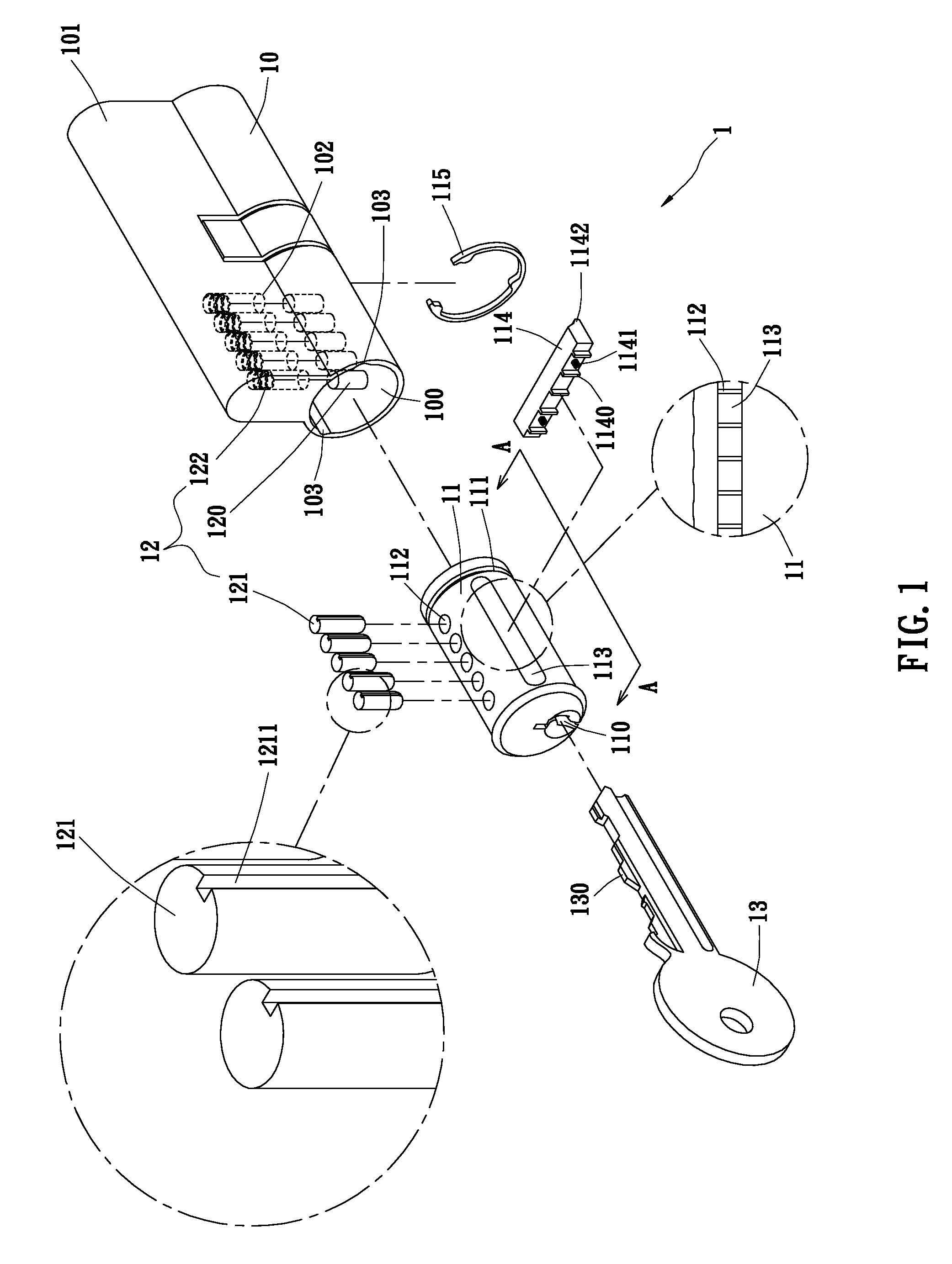
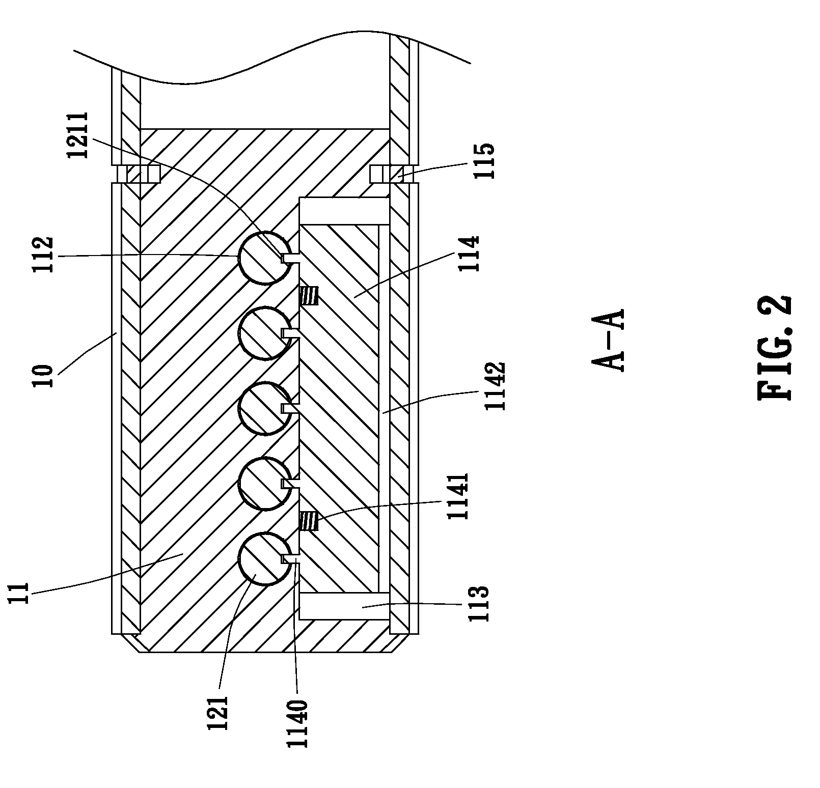
[0022]Referring to FIGS. 1 and 2, a cylinder lock 1 in accordance with a first preferred embodiment of the invention is shown. The cylinder lock 1 comprises the following components as discussed in detail below.

[0023]A cylinder lock casing 10 is intended to be mounted in, for example, a door to be locked in relation to a frame. Alternatively, the cylinder lock casing 10 may constitute a padlock. The cylinder lock casing 10 comprises an axially extending cavity 100 of circular cross-section, two opposite lengthwise grooves 103 on an upper portion of an inner surface of the cavity 100, and a lengthwise riser 101 extending upward from the cavity 100, the riser 101 having a top of arc cross-section and having a plurality of (e.g., five) upper holes 102 aligned along and being in communication with a top of the cavity 100.

[0024]A cylindrical cylinder lock core 11 is rotatably fitted in the cavity 100 and comprises a key hole 110 on an outer end surface, an annular groove 111 proximate an...


PUM


Abstract

A cylinder lock includes a cylinder lock casing comprising an axial cavity, two opposite lengthwise grooves on the cavity, and an upper riser including aligned upper holes being in communication with the cavity; a cylinder lock core releasably fastened in the cylinder lock casing and comprising a key hole, top lower holes, and a side slot being in communication with the key hole, a locking tumbler comprising cylindrical lower tumbler elements slidably disposed in the lower holes, each lower tumbler element partially extended into the key hole and including an outer longitudinal trough, and spring depressible upper tumbler elements in the upper holes and partially disposed in the lower holes to contact with the lower tumbler element; and a spring depressible side bar in the slot and comprising inner ribs and a longitudinal outer protrusion in one groove.

Description

BACKGROUND OF THE INVENTION[0001]1. Field of Invention[0002]The invention relates to cylinder locks and more particularly to a cylinder lock with improved characteristics including increased anti-picking performance.[0003]2. Description of Related Art[0004]Cylinder locks have been used for many years. There have been numerous suggestions in prior patents for cylinder locks. For example, U.S. Pat. No. 4,154,070 discloses a lock that causes insertion of multiple bolts into the jamb surrounding the door in multiple directions. The disadvantage of this patent is that in order to install the device, a large section of the door interior volume needs to be removed, which is a difficult, time consuming and expensive process. In addition, the door structure itself is substantially weakened, reducing overall security. The lock is made of thin sheet metal and is not strong enough.[0005]U.S. Pat. No. 6,490,898 discloses a cylinder lock including a cylinder having a series of locking tumblers wh...

Claims


Application Information

Patent Timeline
Patent Type & Authority Applications(United States)
IPC IPC(8): E05B27/00E05B9/00
CPCE05B27/0039E05B2027/0025E05B27/0082E05B27/0078Y10T70/8459Y10T70/7593
Inventor CHUNG, SHU-LING
Owner CHUNG SHU LING
Why Eureka
Try Eureka