Geotechnical articles

a geotechnical and polymer technology, applied in the field of polymer soil reinforcing and geotechnical articles, can solve the problems of poor puncture resistance of hdpe and mdpe at cold temperatures, difficult installation and sometimes impossible, and high creeping tendency, so as to improve the tear resistance, improve the creep resistance, and improve the effect of crack growth resistan

Inactive Publication Date: 2008-09-04
PRS MEDITERRANEAN
View PDF9 Cites 35 Cited by
  • Summary
  • Abstract
  • Description
  • Claims
  • Application Information

AI Technical Summary

Benefits of technology

[0024]There is still a need for a geotechnical article, especially a CCS, that has excellent creep resistance, including at temperatures of about 400C, a lower CTE, improved tear resistance, and high crack growth resistance at temperatures ranging from about minus 70° C. to about +90° C., maintains enough flexibility to enable installation and GRM filling at temperatures as low as minus 40° C., provides improved welding quality and strength compared to HDPE-based CCSs, especially under continuous loads at temperatures below minus 15° C., and provides improved resistance against UV and heat degradation. Such a CCS would be useful in cold areas of the earth.

Problems solved by technology

If the CCS wall is too flexible, it will collapse during installation in the field, for example when humans walk over the CCS before it is filled with GRM or during the filling and condensing of GRM in the CCS cells.
However, installation becomes difficult and sometimes impossible at subzero temperatures, especially temperatures below minus 10° C. HDPE also has high tendency to creep at temperatures of about +40° C. and over.
HDPE and MDPE also have poor puncture resistance at cold temperatures.
At temperatures lower than minus 10° C., these polymers are no longer tough and ductile, but fragile and brittle.
Creep of the CCS wall causes loosening of the friction and loss of structural functionality of the CCS-GRM composite structure.
Anytime the load transfer between those two components is breached—due to cell wall creep, rupture or irreversible deformation—the filled CCS structure loses its integrity and cannot provide the required structural strength, dimensional stability and stiffness.
The mechanism of failure of CCSs made from HDPE at sub-zero temperatures is complex.
When the stress is applied for many days at temperatures lower than minus 15° C., the toughness of the HPDE or MDPE is insufficient and a brittle failure occurs.
Since crack growth resistance (toughness) of HDPE and MDPE is medium or even low relative to LLDPE or elastomers at those temperatures, the CCS breaks and loses its integrity.
However, if LLDPE or elastomers are used as the matrix of the CCS, then the CCS severely creeps at temperatures greater than 40° C. Thus, the repeated cycles of heating, expansion of the CCS, resultant spreading or collapse of the GRM structure previously contained by the CCS, results in eventual failure or significant loss of function of the CCS.
This brittleness also impacts CCSs.
In particular, this brittleness critically affects the weld points between the plurality of strips.
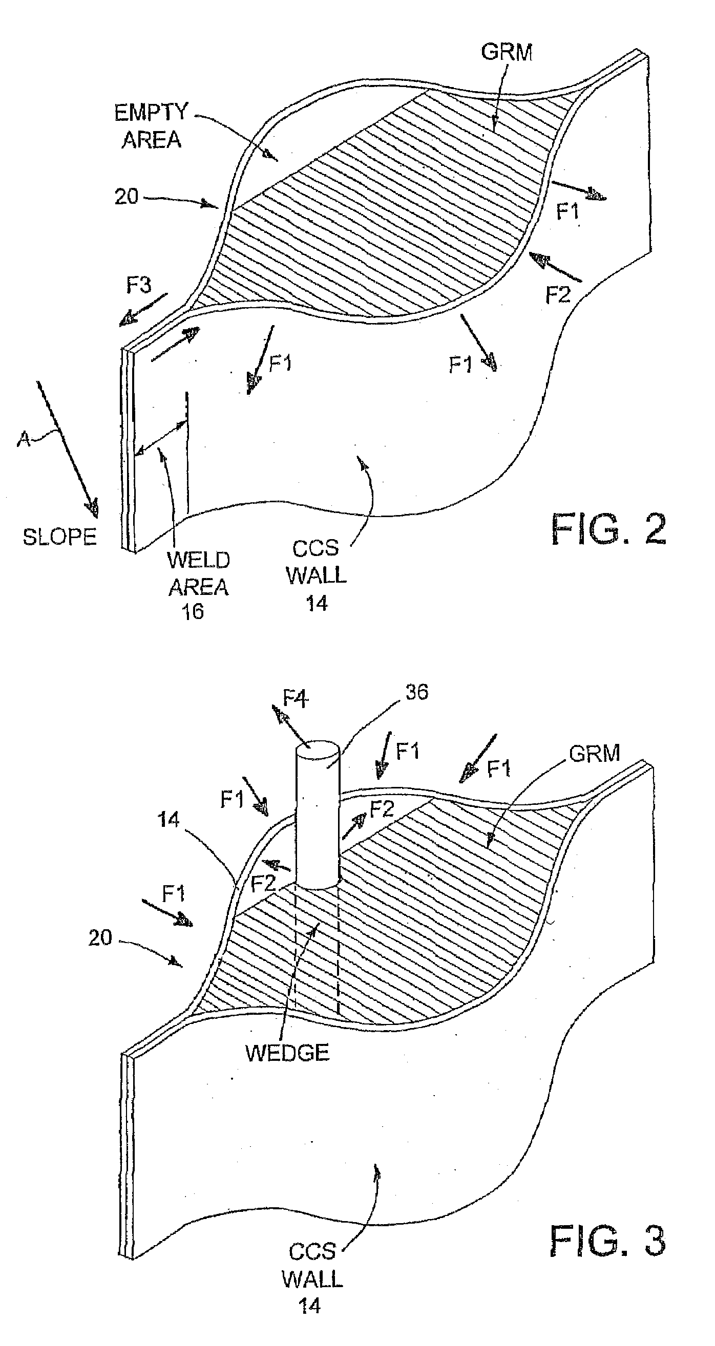
Because the connection points between the CCS and the anchors, tendons, and / or wedges have high loads concentrated in a small area, failure is most likely to happen at these stress concentration points, especially under extreme conditions such as subzero temperatures or temperatures higher than about 40° C.
HDPE also has relatively poor stress cracking resistance, medium to low tear and puncture resistance, and low crack growth resistance—especially at subzero temperatures.
Cracks are initiated in geotechnical applications during application and installation, and during service, especially when dynamic loads are applied.
Since the brittleness increases in a “quasi-exponential” fashion as temperature drops, reinforcing articles comprising HDPE as the major constituent are subjected to catastrophic failure at subzero (° C.) temperatures.
Again, failure is more likely to happen at the weld points and at the contact points between the CCS and wedges, anchors, and tendons.
However, they have very poor creep resistance at temperatures higher than ambient, and especially higher than 40° C. Such high temperatures are expected in arid and tropic areas, but are also reached in cold areas (e.g., during the summer).
Another drawback of relatively flexible polymers (such as LLDPE) is that they lack the stiffness needed when the CCS cells are still empty and humans need to walk on it during installation or during filling and compaction of GRM.
If the CCS wall is too flexible, it will collapse during installation in the field, especially during the filling and condensing of GRM in the CCS cells.
They also tend to creep under load, so that the connection points to anchors, tendons, and / or wedges get loose over time in elevated temperatures.
This creep undermines the integrity of the CCS.
These polymers are made in a reactor and thus very limited in composition flexibility.
If a more rubbery phase is required, it cannot be made in a reactor.
The compositions described in this patent are not applicable for structural geotechnical applications including CCSs, due to its inherent brittleness, especially at low temperatures, and lack of protection against humidity and UV light.
This patent does not deal with either the difficulties in welding of the compositions, or the hydrolytic instability of the polyamide phase, which may be hydrolyzed in soil, especially acidic soils.
However, LLDPE itself does not provide adequate flexibility at low temperatures.
Blending in standard manufacturing equipment does not provide the morphology that is required for long-term stability when the temperature of the exposed plastic can vary from minus 70° C. to +90° C. This is a problem especially in cold areas where during autumn and winter, the temperature of exposed plastics may drop below minus 40° C., but during summer, when direct sunlight is absorbed by the CCS surface, temperatures may exceed +90° C.
Other drawbacks related to this mixing of two polyethylenes for geotechnical articles are the still high CTE (higher than about 150 ppm / ° C.
), poor heat conductivity, high creep under loads provided during thawing of water in the GRM pores, limited chemical resistance to oils and fuels (for example oilfields in Alaska and Siberia), and difficulties in high throughput extrusion of film and strips due to the low melt flow index of LLDPE.
Consequently, in extrusion applications, for example extrusion of strips for geotechnical applications, flow of the melt is uneven (melt fracturing), and segregation between phases is observed.
The compositions described in this patent are not applicable for structural geotechnical applications including CCSs, due to their flexibility and creep tendency.
The patent also does not provide a solution for the protection of the blend from hydrolysis in soils and landfills, oils and hydrocarbons, and from the degradation induced by heat and UV light.
Another drawback is that LLDPE is not flexible enough and lacks the required toughness when it reaches temperatures lower than minus 40° C.
PP is too rigid and lacks the flexibility at temperatures below about 0° C., a property that is mandatory in CCSs.
The compatibilizer in this patent is styrene-based and thus has limited UV light resistance, limiting the composition lifetime to about 1 to 2 years.
Polyester blends, especially when not specially stabilized against hydrolysis, may fail in soils, especially those having pH greater than 7, within a relatively short period of time.
Another drawback is that the blend is not flexible enough and lacks the required toughness when it reaches temperatures lower than minus 40° C.
The incorporation of the more amorphous LLDPE into the HDPE resin provides crack stop mechanisms, but no solution is provided for CCS systems where strength is crucial and creep must be minimized—especially at temperatures greater than 40° C. Moreover, no solution is provided for subzero temperatures such as temperatures below minus 15° C. or minus 40° C. Since CCSs are a composite structure comprising strips and weld lines, mixing two different polyethylenes may negatively affect welding strength and long-term durability as well.
Another disadvantage of blending LDPE or LLDPE with HDPE is that inferior weld strength results.
It is also not straightforward to disperse the relatively viscous LLDPE in an HDPE matrix, especially by means of conventional extrusion equipment.
The high flexibility that is an 
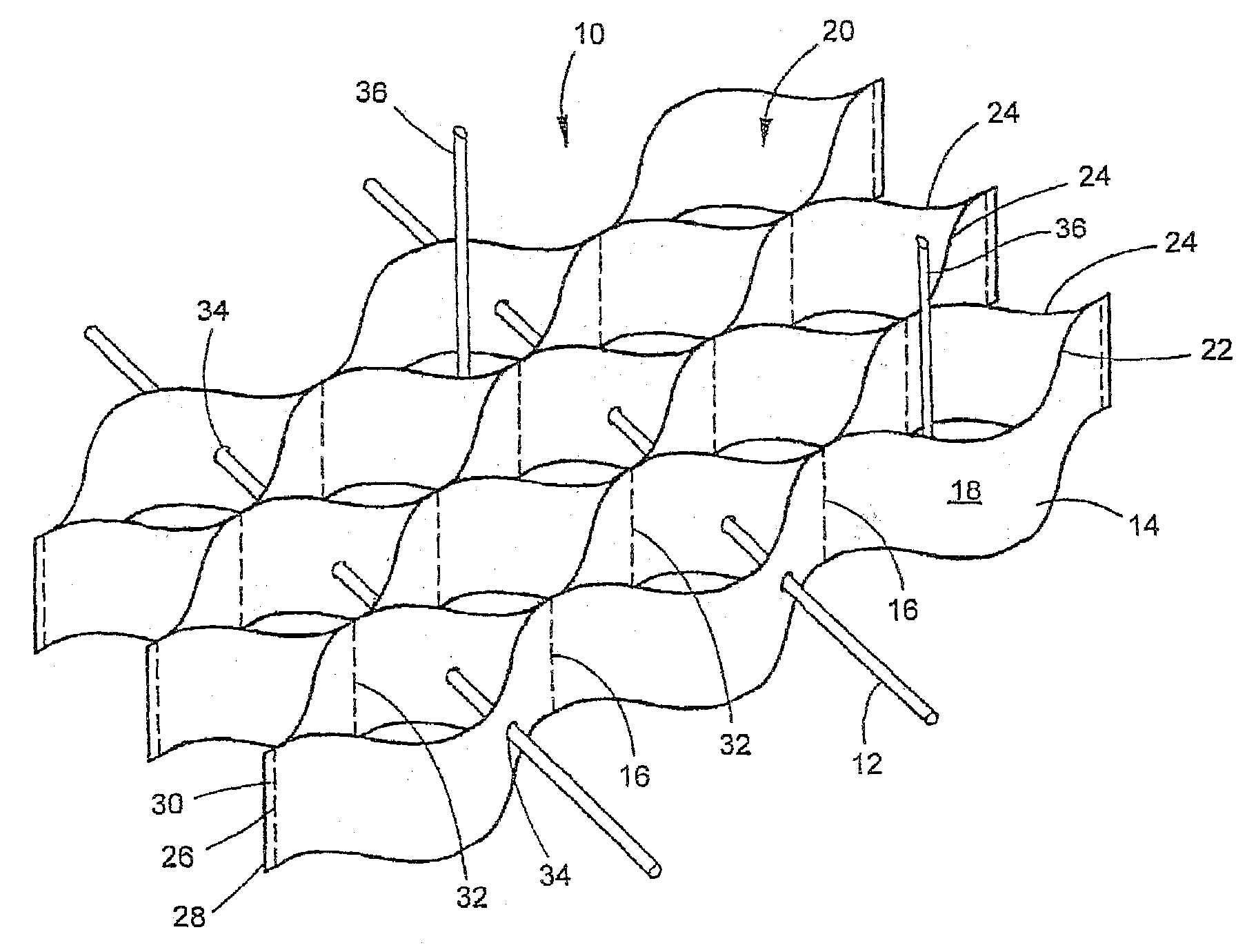
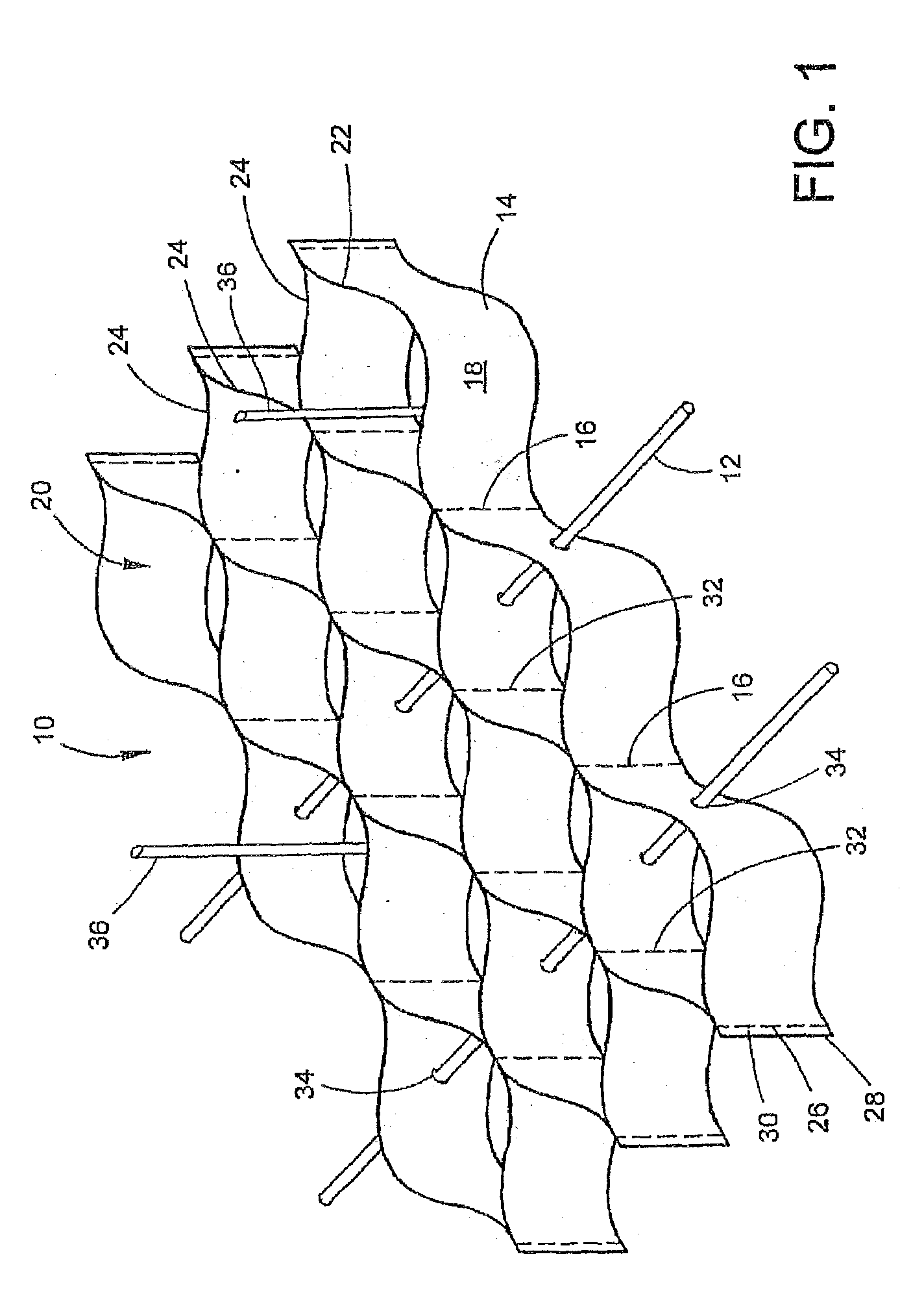
advantage in geomembranes becomes a drawback in CCS: when load is applied on CCS supporting GRM, the composite structure of the two components interacts with the load as an integrated system.
At that specific state, the integrated system is irreversibly damaged and can no longer provide the required durability, stiffness and stabilization to the GRM.
The patent does not provide a solution to the hydrolysis of the composition in soils and landfills, or when exposed to concrete or other media characterized by pH of greater than 7.
The flexible blend has a CTE greater than 150 ppm / ° C. and also does not provide sufficient toughness at temperatures lower than minus 40° C.

Method used


Image

  • Geotechnical articles
  • Geotechnical articles
  • Geotechnical articles

Examples


example 1

[0135]A MPM composition was made comprising 70-90 weight percent Marlex® K306 MDPE (manufactured by Chevron Philips) having a density of 0.937 g / cm3, 5-40 weight percent Marlex® 7104 LLDPE (manufactured by Chevron Philips) having a density of 0.918 g / cm3, 0-25 weight percent Engage® 8100 metallocene plastomer (manufactured by DOW), and up to 30% calcium carbonate or talc filler having an average particle size of less than 10 microns. The ingredients were melt kneaded in a co-rotating twin screw extruder characterized by L / D ratio of about 40, equipped with at least one side feeder for the filler, one atmospheric vent and one vacuum vent for degassing. The resulting MPM compound was pelletized. The pellets were dried and re-melted in a second single screw extruder at a melt temperature of about 160-280° C. and pumped through a die to form a sheet. The sheet was cooled between metal chilling rolls. Two formulations made according to this procedure are described in Table 1 as Formulas ...

example 2

[0136]MPM composition was made comprising 50-80 weight percent SABIC® HDPE B5411 (manufactured by Sabic) having density of 0.954 g / cm3, 0-40 weight percent Marlex® 7104 LLDPE (manufactured by Chevron Philips) having density of 0.918 g / cm3, 5-40 weight percent Exact® 201 plastomer (manufactured by ExxonMobil) having density of 0.902 g / cm3, 0-20 weight percent PET dry regrind, about 10 weight percent maleated polyethylene (Bondyram™ 5001 manufactured by Polyram), and 0-40 weight percent calcium carbonate or talc filler having an average particle size of less than 10 microns. The ingredients were melt kneaded in a co-rotating twin screw extruder characterized by L / D ratio of about 40, equipped with at least one side feeder for the filler, one atmospheric vent and one vacuum vent for degassing. The resulting MPM compound was pelletized. The pellets were dried and re-melted in a second single screw extruder at a melt temperature of about 160-280° C. and pumped through a die to form a she...


PUM

PropertyMeasurementUnit
temperatureaaaaaaaaaa
flexural modulusaaaaaaaaaa

Abstract

A multiphase polymeric material comprises a first rigid continuous phase and a second elastic phase dispersed in the first phase. The multiphase polymeric material may be formed into polymeric strips and used to make a cellular confinement system which is suitable for use in cold areas.

Description

CROSS-REFERENCE TO RELATED APPLICATIONS[0001]This application is related to U.S. Patent Application Serial No. (PRSI 200002), filed concurrently and entitled “UV RESISTANT MULTILAYERED CELLULAR CONFINEMENT SYSTEM”; and to U.S. Patent Application Serial No. (PRSI 200004), filed concurrently and entitled “HIGH PERFORMANCE GEOSYNTHETIC ARTICLE”; to U.S. Provisional Patent Application Serial No. (PRSI 200005), filed concurrently and entitled “WELDING PROCESS AND GEOSYNTHETIC PRODUCTS THEREOF”; and to U.S. Provisional Patent Application Serial No. (PRSI 200006), filed concurrently and entitled “PROCESS FOR PRODUCING COMPATIBILIZED POLYMER BLENDS”. All four of these patent applications are hereby incorporated by reference in their entirety.BACKGROUND[0002]The present disclosure relates to polymeric soil reinforcing and geotechnical articles. Strips, sheets, profiles, and cellular confinement systems are made from polymer compositions, such as a multiphase polymeric material, which are opt...

Claims


Application Information

Patent Timeline
Patent Type & Authority Applications(United States)
IPC IPC(8): B29D22/00D06N7/00
CPCC08L21/00B29C47/0019B29C47/0033B29C47/0021B29C66/47B29C66/71B29K2105/16E02D17/202B29K2023/065B29C65/8215B29C66/826B29C65/08B29C66/73111B29K2023/0625B29C66/731C08L23/16B29K2023/00C08L75/04B29K2105/005B29K2101/12B29C66/7313B29C66/438C08L9/02B29K2023/22C08L23/06B29C66/437B29K2105/0044Y10T428/24628Y10T428/24661B29L2031/608C08L67/00Y10T428/24149C08L53/02B29C47/0038B29K2067/00B29K2105/0032B29C65/823Y10T428/24165B29C66/7352B29C65/483B29K2021/00Y10T428/1352B29D28/00C08L23/0815B29C66/1122B29C65/02B29C65/48B29K2023/06B29C65/62B29K2075/00B29K2023/0641C08L9/00B29K2077/00B29C65/8207B29C47/00B29C66/9513C08L77/00B29K2105/0085Y10T428/24157B29C65/4825C08L2666/20C08L2666/08C08L2666/18C08L2666/02B29C65/00B29K2995/0089B29K2995/0083B29C66/7315B29C66/73921B29C66/73117B29C66/73774B29C66/712B29C48/07B29C48/13B29C48/08B29C48/001B29C48/00B29C66/73112B29K2083/005B29K2067/003B29K2033/12B29K2033/08B29K2025/08B29K2023/16B29K2023/08
Inventor HALAHMI, IZHAREREZ, ODEDEREZ, ADI
Owner PRS MEDITERRANEAN
Why Eureka
Try Eureka