Rotorcraft with Variable Incident Wing

Active Publication Date: 2010-12-30
TEXTRON INNOVATIONS
View PDF16 Cites 44 Cited by
  • Summary
  • Abstract
  • Description
  • Claims
  • Application Information

AI Technical Summary

Problems solved by technology

Both of these options have significant disadvantages.
For example, with the former, a flexib

Method used


Image

  • Rotorcraft with Variable Incident Wing
  • Rotorcraft with Variable Incident Wing
  • Rotorcraft with Variable Incident Wing

Examples


Embodiment Construction

[0021]Illustrative embodiments of the invention are described below. In the interest of clarity, not all features of an actual implementation are described in this specification. It will of course be appreciated that in the development of any such actual embodiment, numerous implementation-specific decisions must be made to achieve the developer's specific goals, such as compliance with system-related and business-related constraints, which will vary from one implementation to another. Moreover, it will be appreciated that such a development effort might be complex and time-consuming but would nevertheless be a routine undertaking for those of ordinary skill in the art having the benefit of this disclosure.

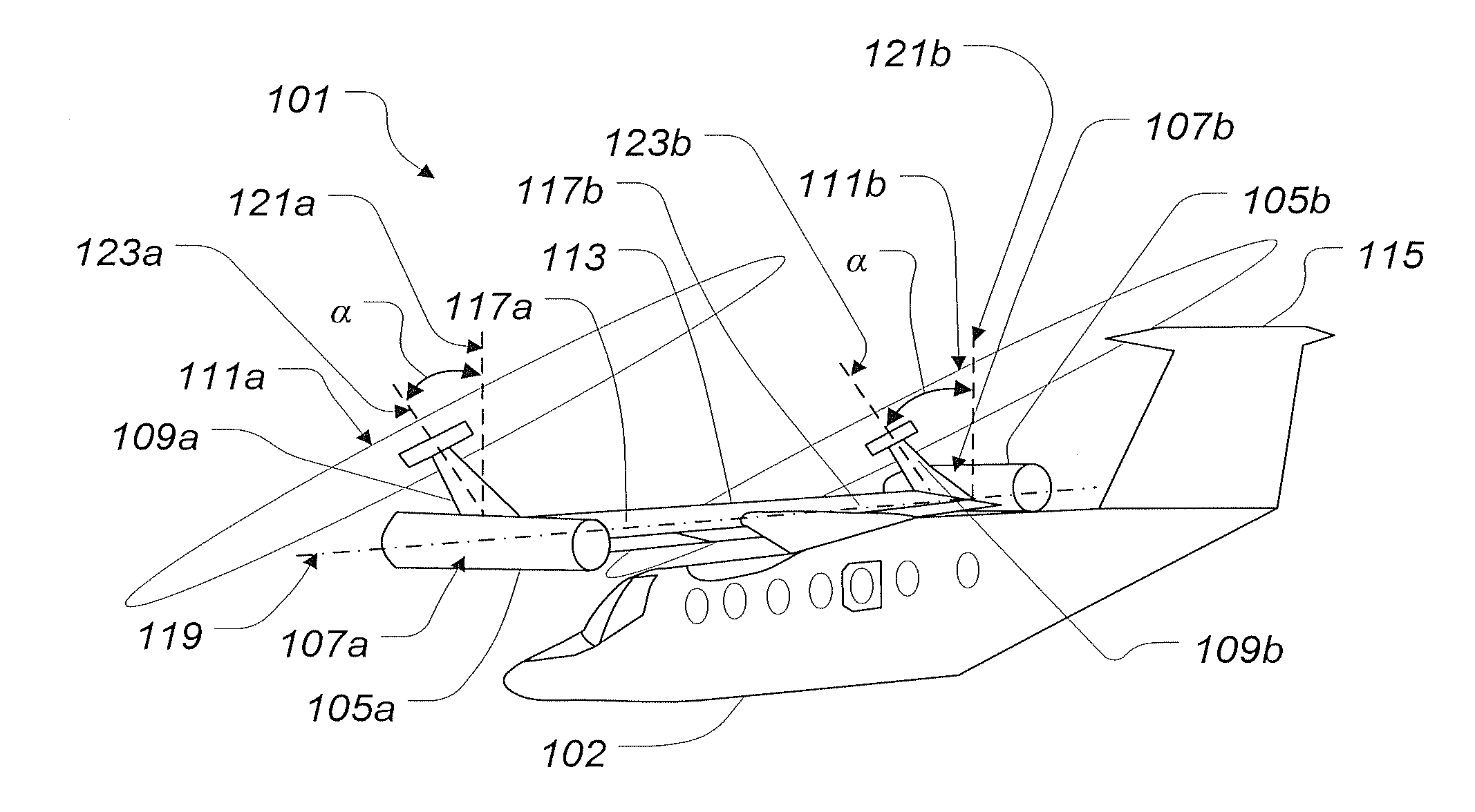
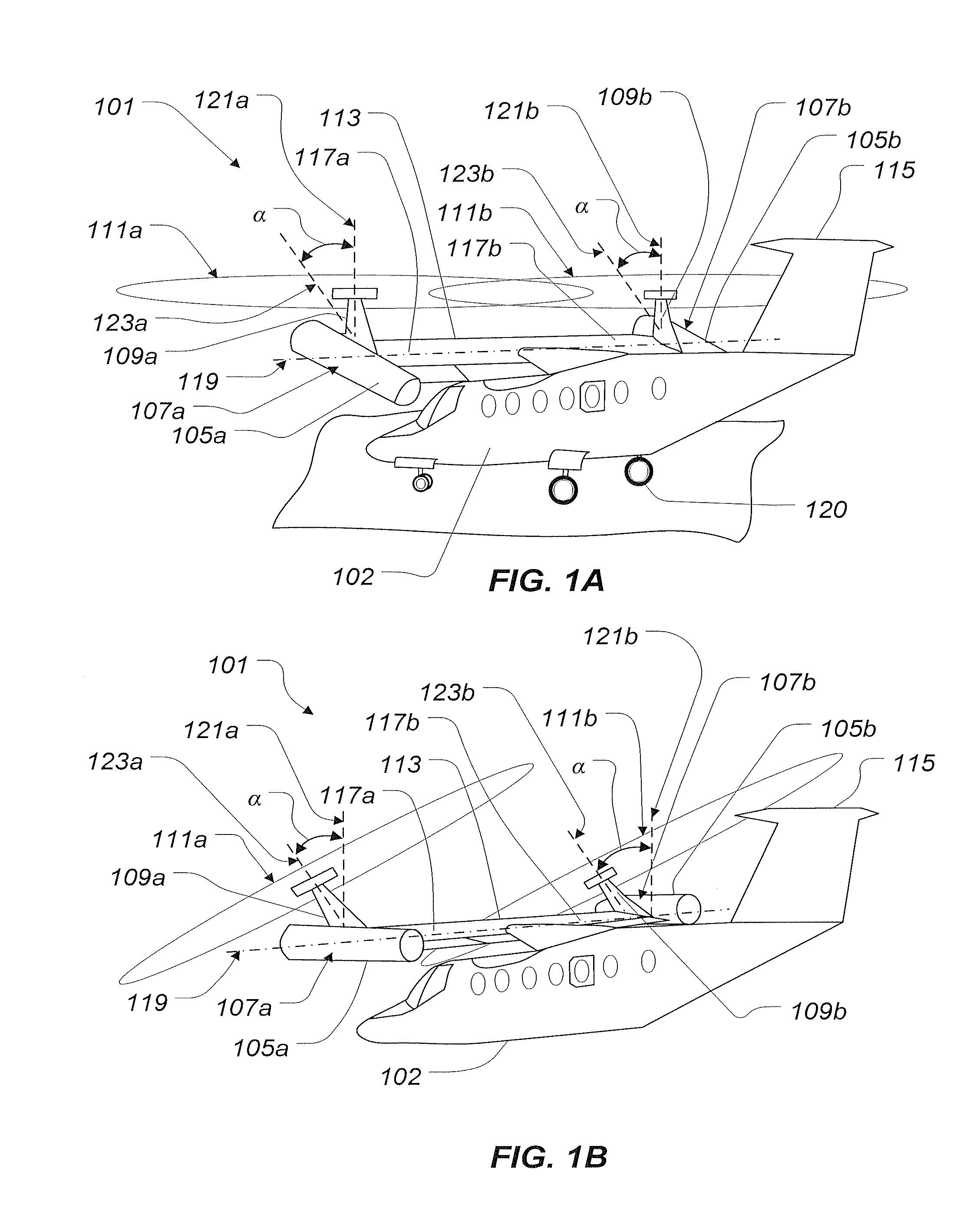
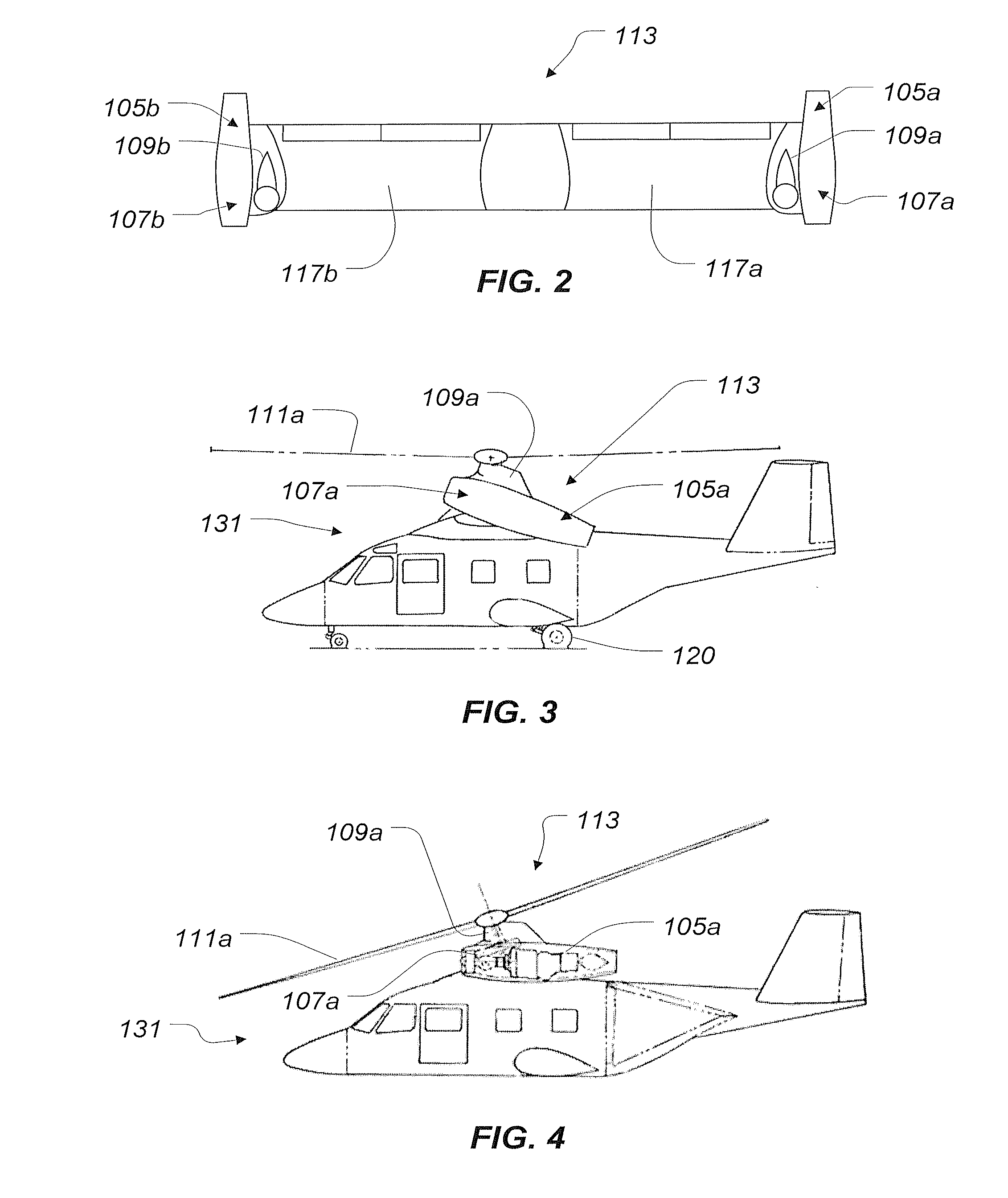
[0022]The invention of the present application relates primarily to high-speed helicopter / rotorcraft configuration concepts. The rotorcraft according to the present application provides a unique solution to the high-speed problems of retreating blade stall and rotor flapping speed...


PUM


Abstract

A twin-rotor side-by-side compound rotorcraft has a fuselage and variable incident wing assembly that pivots relative to fuselage. The aircraft also has landing gear assembly and a tail fin assembly. The variable incident wing assembly is pivotally attached to the fuselage, and includes wing members, engines fixedly mounted to the wing members or another area of the rotorcraft, and a mast attached at a fixed angle relative to the wing members. Then engines may also be located near the fuselage or another area of the rotorcraft. The variable incident wing assembly is capable of pivoting about a pivot axis, thereby allowing mast orientation in at least a hover mast position and a forward flight mast position. The rotors provide additional forward thrust and the wings provide additional lift, when the mast is in the forward flight mast position.

Description

TECHNICAL FIELD[0001]The present invention relates to helicopters and other rotorcraft.DESCRIPTION OF THE PRIOR ART[0002]In simple terms, conventional helicopters have a fuselage, a main rotor, and a tail rotor. Each rotor has multiple rotor blades and is powered by an engine. Power generated by the engine is transmitted to the rotors via shafts, transmissions, and gear boxes. The main rotor is coupled to the engine via a rotor mast.[0003]It is often desirable to have a mast with a variable angle of incidence relative to the fuselage to provide more forward thrust. There are various ways of obtaining variable mast incidence on conventional helicopters, including: (1) utilizing a tilting of the mast / transmission assembly realtive to the fuselage and engine; or (2) utilizing a tilting mast / transmission / engine assembly. Both of these options have significant disadvantages. For example, with the former, a flexible drive shaft is required; and with the latter, a complicated mounting syst...

Claims


Application Information

Patent Timeline
IPC IPC(8): B64C27/22
CPCB64C27/26B64C27/28B64C29/0033B64C3/385B64C27/52B64C37/00
Inventor SMITH, DUDLEY E.JOINER, WALTER C.ROBERTSON, DANIEL B.LUDOLPH, DAVID J.LANGSTON, JENNIFER D.
Owner TEXTRON INNOVATIONS
Why Eureka
Try Eureka