
Lens module for forming stereo image

Inactive Publication Date: 2010-12-30
HON HAI PRECISION IND CO LTD
View PDF4 Cites 0 Cited by
  • Summary
  • Abstract
  • Description
  • Claims
  • Application Information

AI Technical Summary

Benefits of technology

[0002]The disclosure relates to lens modules and, more particularly, to a lens module for forming a stereo image.

Problems solved by technology

However, the conventional system including the two cameras has a high cost and is bulky.

Method used

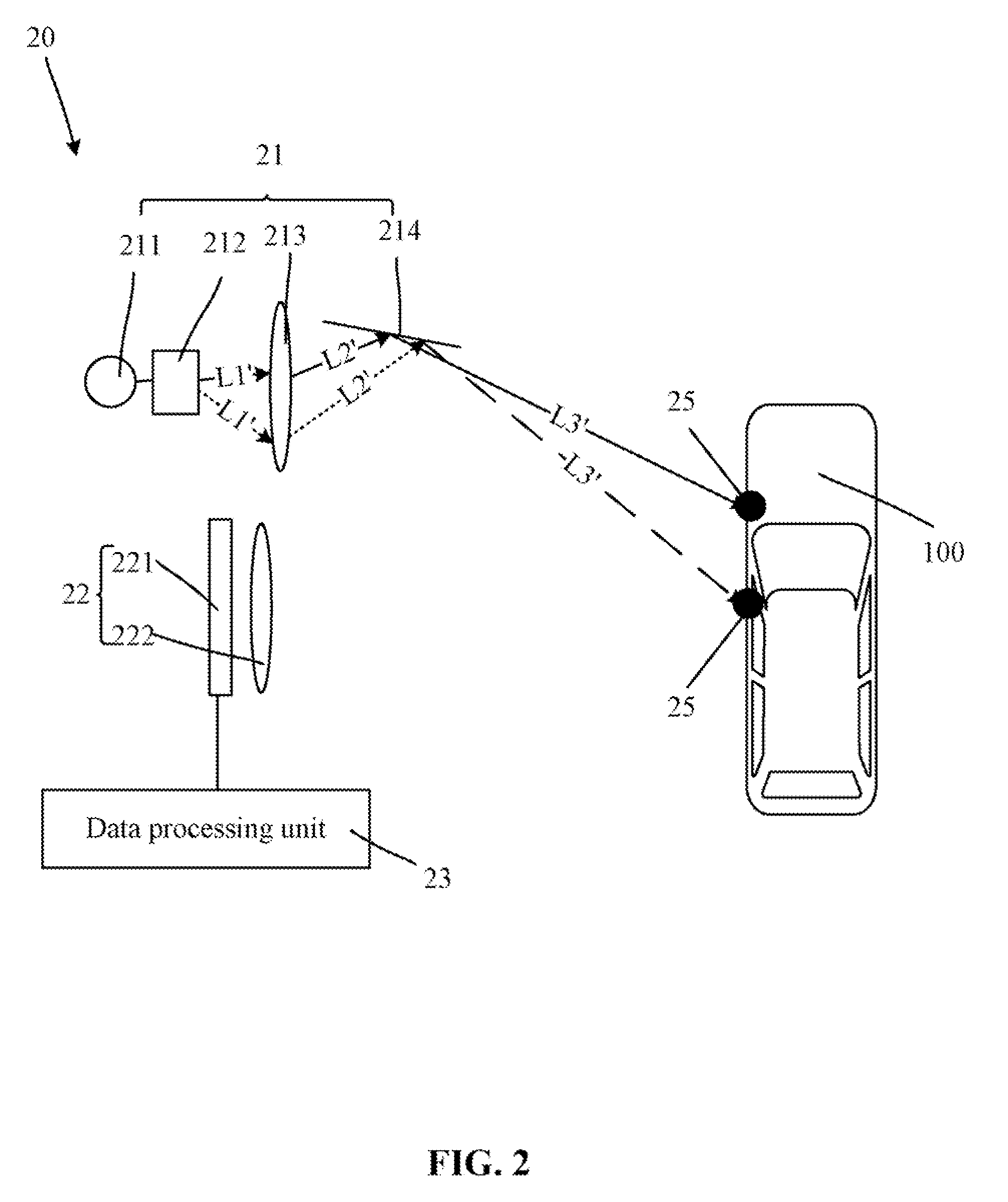

Image

  • Lens module for forming stereo image
  • Lens module for forming stereo image
  • Lens module for forming stereo image

Examples


Embodiment Construction

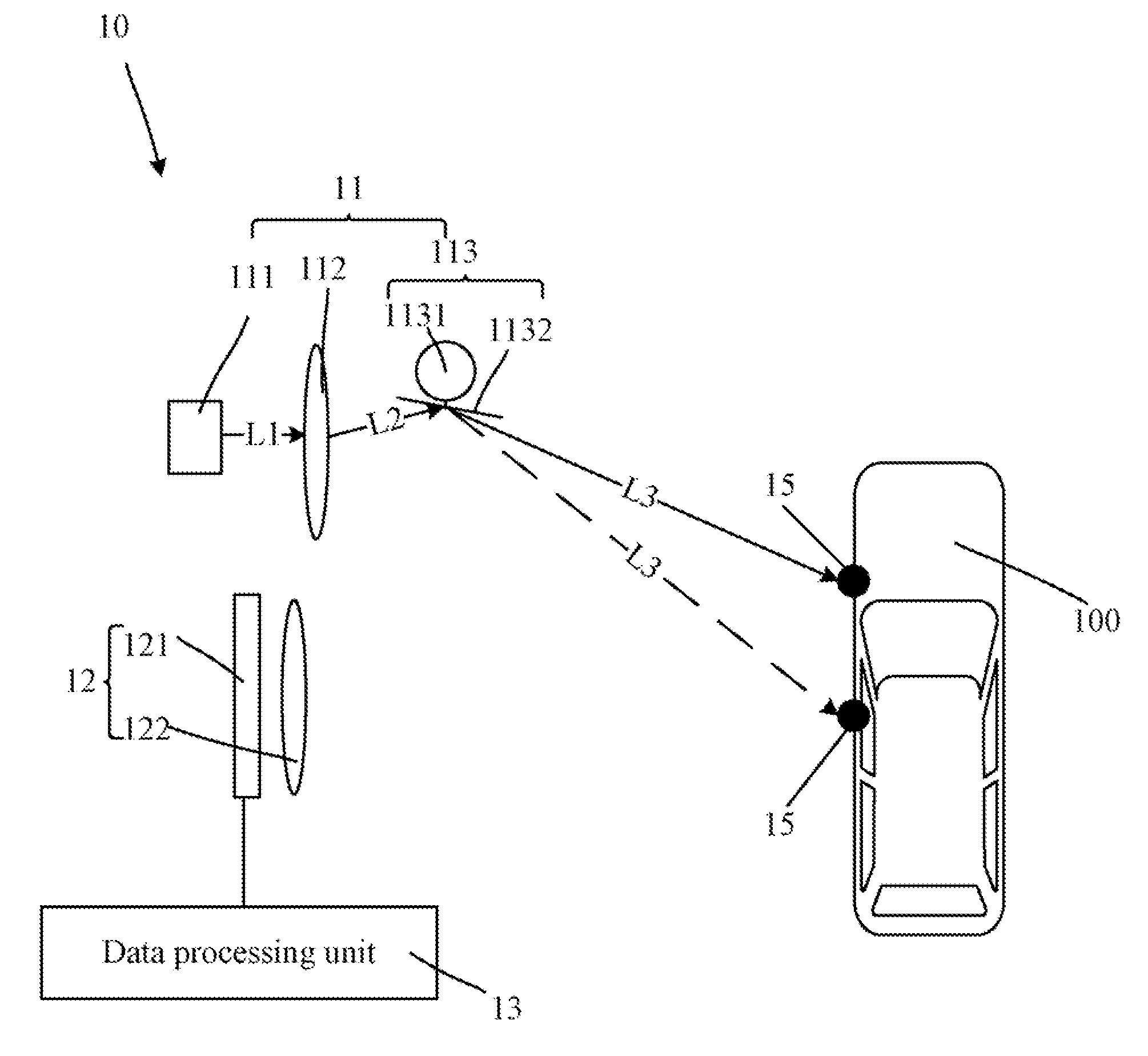
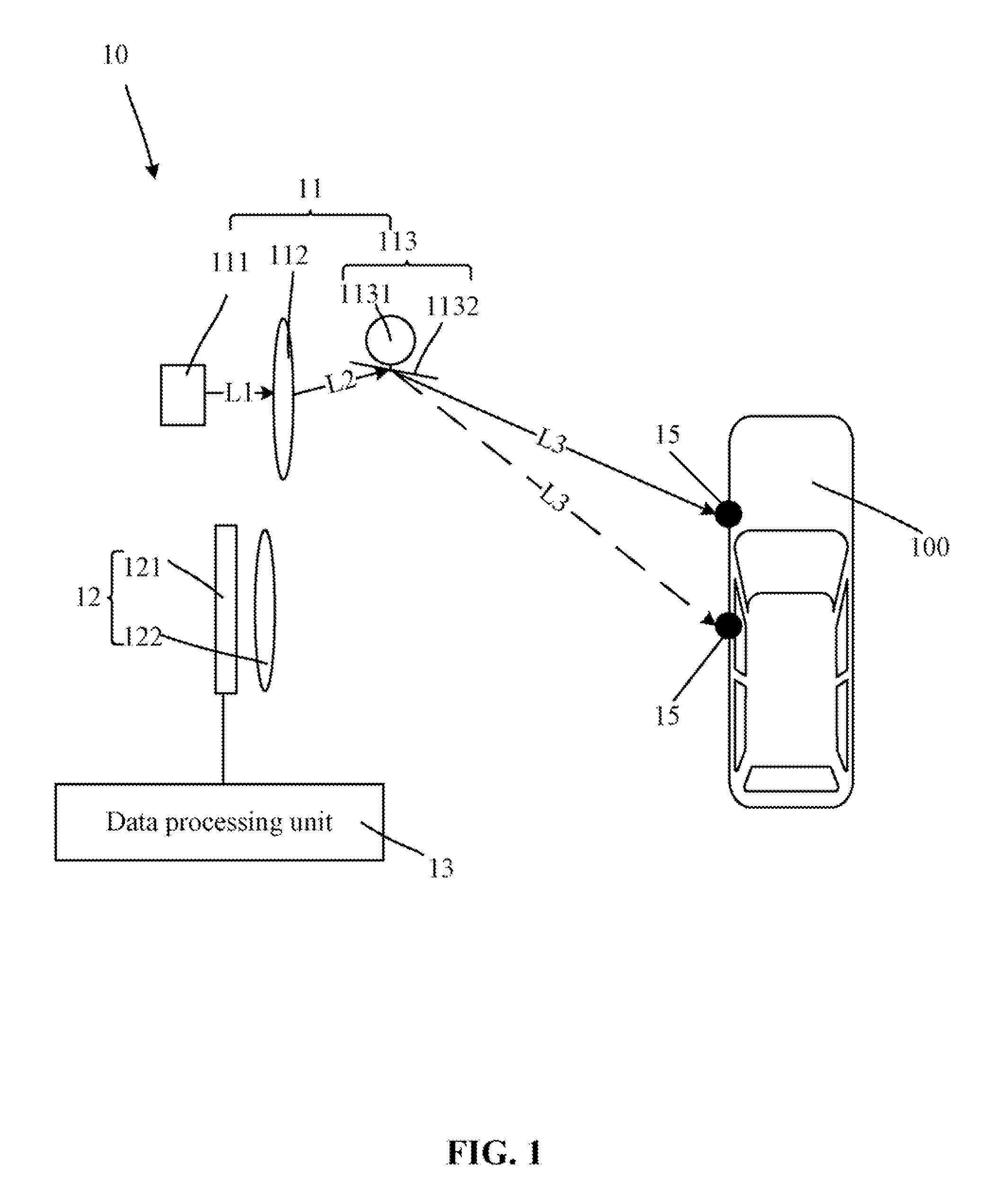
[0008]FIG. 1 is a schematic view of a lens module for forming a stereo image in accordance with an embodiment. The lens module for forming a stereo image (hereinafter “the lens module”) 10 includes a light-scanning unit 11, a camera sensor unit 12, and a data processing unit 13. The light-scanning unit 11 further includes a point light source 111, a collimating lens 112, and a two-dimensional scanning module 113. The collimating lens 112 is configured for collimating light from the point light source 111. The two-dimensional scanning module 113 is configured for controlling the light to project onto an object 100 to obtain image points 15, which are reflected and arrayed in a matrix on the object 100. The two-dimensional scanning module 113 is further configured for scanning the image points 15.

[0009]The two-dimensional scanning module 113 further includes a motor 1131 and a flat mirror 1132. The motor 1131 is configured for manipulating the flat mirror 1132 to rotate according to p...


PUM


Abstract

The disclosure provides a lens module for forming a stereo image. The lens module includes a point light source, a two-dimensional scanning unit, a camera sensor unit, and a data processing unit. The two-dimensional scanning unit is configured for controlling the light from the point light source to project onto an object to obtain image points, which are reflected and arrayed in a matrix on the object and scanning the image points. The camera sensor unit is configured for receiving the light reflected by the object and capturing an image of the image points. The data processing unit is configured for receiving the image from the camera sensor unit and performing an analysis on the image to obtain depth information of the object.

Description

BACKGROUND[0001]1. Technical Field[0002]The disclosure relates to lens modules and, more particularly, to a lens module for forming a stereo image.[0003]2. Description of the Related Art[0004]In a conventional stereo image capturing system, two cameras are needed, wherein, one camera is used for taking a photograph of an object from one angle and the other is used for taking a photograph of the object from another angle. The two images are then integrated into a stereo image of the object according to the relative positions of the two cameras. However, the conventional system including the two cameras has a high cost and is bulky.BRIEF DESCRIPTION OF THE DRAWINGS[0005]The components in the drawings are not necessarily drawn to scale, the emphasis instead being placed upon clearly illustrating the principles of the lens module. Moreover, in the drawings, like reference numerals designate corresponding parts throughout the several views.[0006]FIG. 1 is a schematic view of a lens modul...

Claims


Application Information

Patent Timeline
IPC IPC(8): H04N13/02
CPCG01S17/46H04N13/0253H04N13/0207H04N13/207H04N13/254
Inventor LEE, CHUN-YU
Owner HON HAI PRECISION IND CO LTD
Learn More