Video image display apparatus

Inactive Publication Date: 2010-12-30
SHARP KK
View PDF19 Cites 34 Cited by
  • Summary
  • Abstract
  • Description
  • Claims
  • Application Information

AI Technical Summary

Benefits of technology

[0052]According to the present invention, performing the processing which boosts a signal having a luminance value that is a certain level or lower all the time allows a further brightness feeling to be appealed in a case where a video

Problems solved by technology

Meanwhile, such gain control has a problem that a gain becomes smaller and luminance becomes lower in most pixels for a totally bright video image, and theref

Method used


Image

  • Video image display apparatus
  • Video image display apparatus
  • Video image display apparatus

Examples


example 1

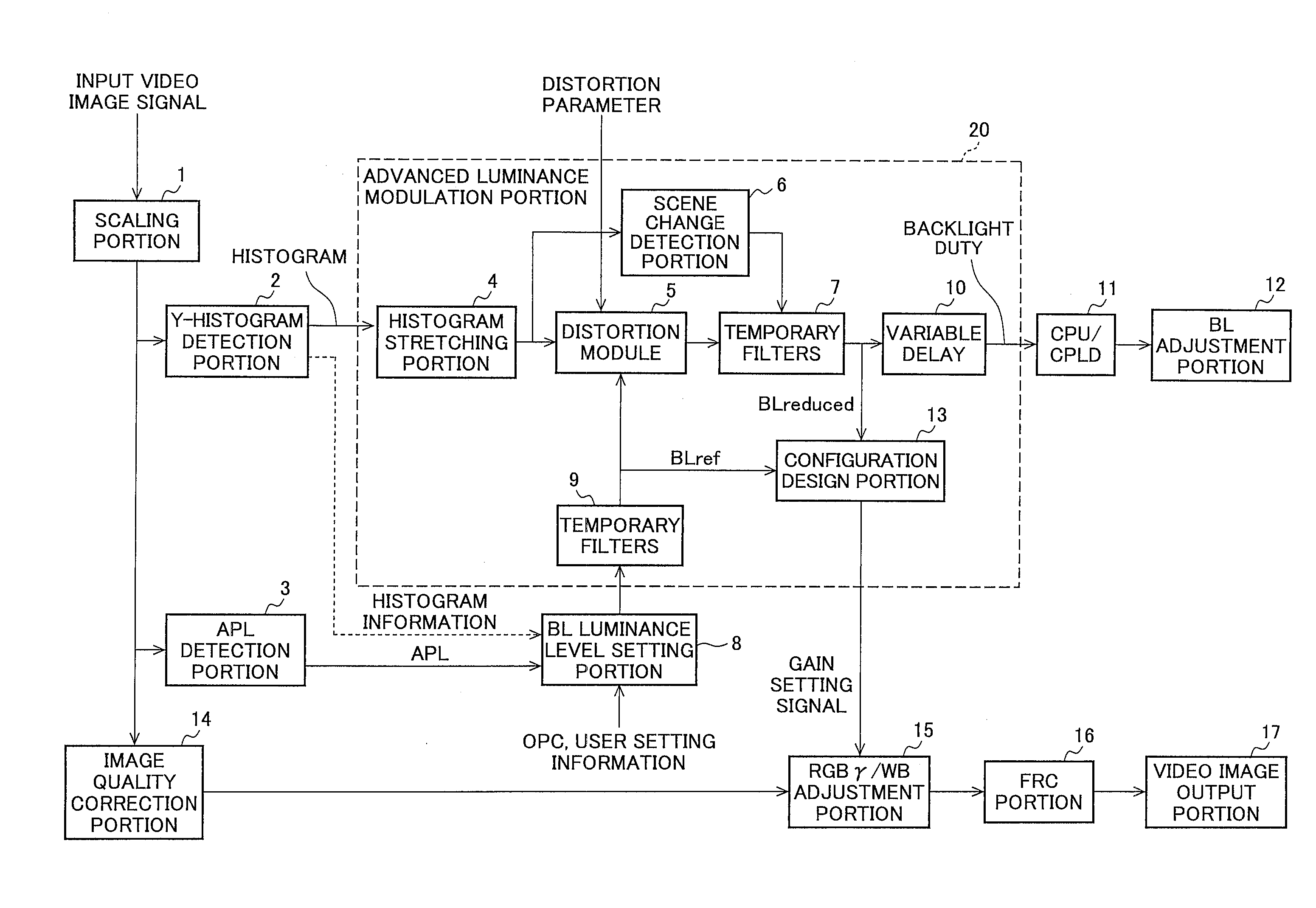
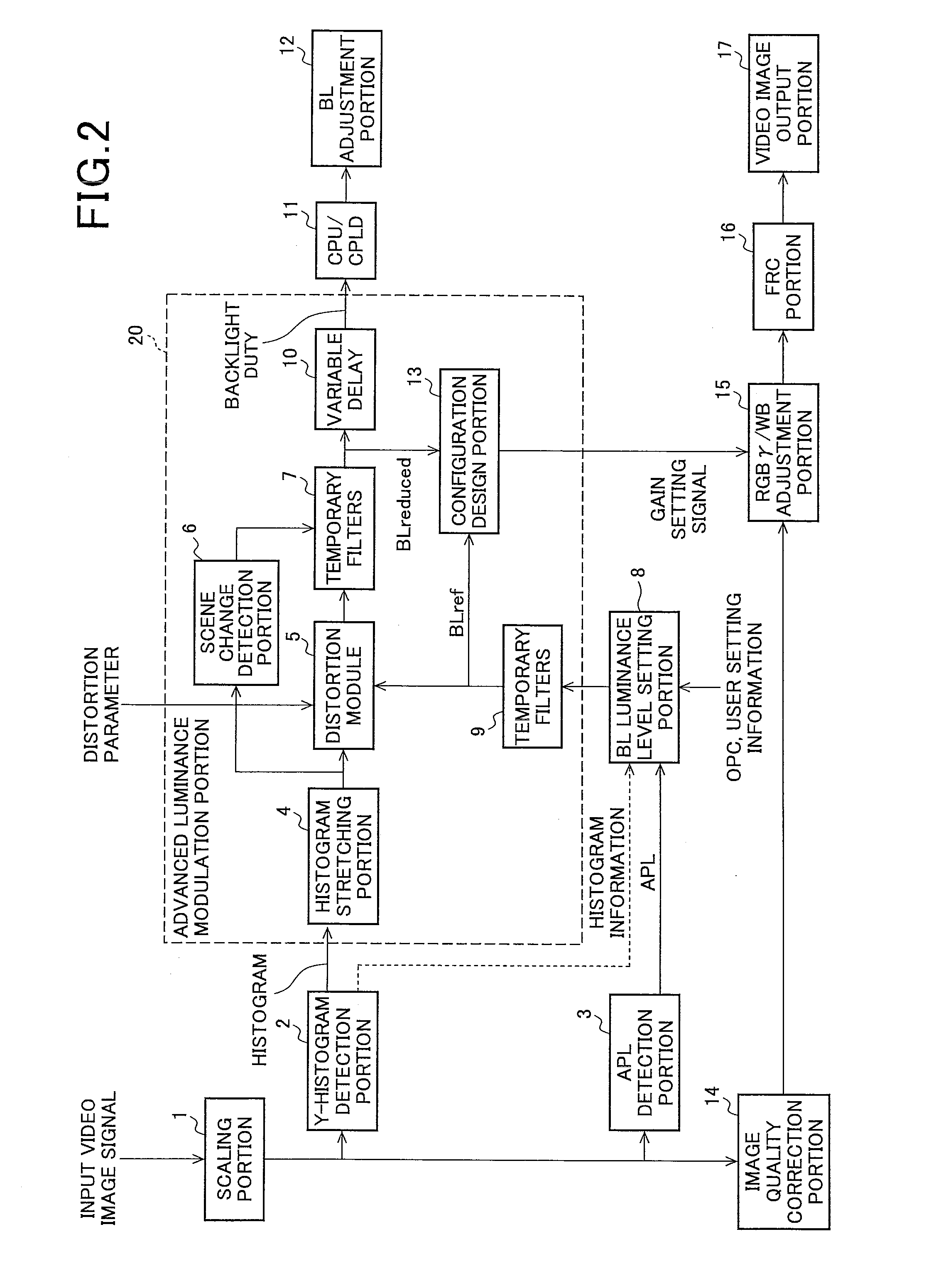
[0167]FIG. 14 is a diagram for explaining an example of the advanced luminance modulation processing applicable to the video image display apparatus of the present invention. In this example, a video image of an intermediate luminance is expressed in brighter and higher contrast, and it makes possible to express a high luminance video image in a clear display avoiding clipped whites and also to express for a low luminance video image with an improved black level.

[0168]In this example, an APL is used as a video image characteristic amount to determine the luminance control properties, and the light emission luminance level for reference is set to be a value greater than 100% that is originally not able to be output to perform an expression of a video image of an intermediate luminance to be brighter and higher in contrast, when the APL of the video image signal is in the middle level.

[0169]Various settings in this example are as follows.

[0170]a) a panel CR (contrast ratio of a panel ...

operation example 1-1

[0182]In this operation example, an input video image signal is assumed to be a video image whose histogram of video image signals is distributed in high luminance values around 255 in the histogram, and an APL thereof is 90% (video image of a snow scene, for example) as shown in FIG. 15 (A).

[0183]In this case, since a lot of high luminance components are contained in the histogram of the video image signal, a distortion module 5 selects 100% as a light emission luminance level of a backlight light source BLreduced.

[0184]In addition, when the APL is 90%, predetermined conditions of the luminance control properties shown in FIG. 14 (B), namely, the conditions that the APL is a first value L1 or more and is a second value L2 or less are not met, therefore, 100% is set as a light emission luminance level for reference BLRef. Accordingly, again set by a configuration design portion 13 is (100 / 100)1 / 2.2=1, and amplification of the video image is not performed. It is thereby possible to p...

operation example 1-2

[0185]In this operation example, an input video image signal is assumed to be a video image whose histogram of video image signals is distributed in high luminance values around 255 and also distributed around low luminance values at not a little rate, and an APL thereof is 85% (video image of a person wearing black clothing in a snow scene, for example) as shown in FIG. 15 (B).

[0186]In this case, a high luminance component is much contained in the histogram of the video image signal, therefore, the distortion module 5 selects 100% as a light emission luminance level of a backlight light source BLreduced. This is because pixels that may not be expressed in a high luminance part increase when a light emission luminance of a backlight light is smaller than 100%, and a value of evaluation value (Distortion) is caused to be great.

[0187]In addition, when the APL is 85%, the predetermined conditions of the luminance control properties shown in FIG. 14 (B), that is, that the APL is the fir...


PUM


Abstract

Brightness expression without solid white pattern is enabled, and video expression with an improved black level is achieved. A distortion module (5) reduces the luminance of a backlight source according to the histogram of the video signal so that the contrast may be a predetermined target one. A configuration design unit (13) sets the gain according to the luminance level (BLreduced) of the backlight source selected by the distortion module (5). When setting the gain, the luminance level (BLref) for reference of the backlight source preset according to the video feature value is referenced. If the video feature value meets a predetermined condition, the input video signal is always amplified with the gain. If not, depending on the relation between the BLreduced and the BLref, the input video signal is amplified or not.

Description

TECHNICAL FIELD[0001]The present invention relates to a video image display apparatus for expressing a desired display video image.BACKGROUND OF THE INVENTION[0002]Conventionally, various video image expressions such as gain adjustment of a video image signal and enhancement of a contrast are tried (for example, Patent Document 1).[0003]When a powerful video image expression is tried, processing for enhancing screen luminance is given because a brightness feeling of a screen is required. In this point, Patent Document 2 describes that, conventionally, a video image display is performed by increasing a gain for a pixel that is in a low to intermediate region of gamma correction properties for making a brightness feeling of a display video image and by decreasing a gain for a high region pixel to prevent saturation in a bright pixel at the same time.[0004]Meanwhile, such gain control has a problem that a gain becomes smaller and luminance becomes lower in most pixels for a totally bri...

Claims


Application Information

Patent Timeline
IPC IPC(8): H04N9/74
CPCG09G3/20G09G3/3406G09G3/3611G09G2320/0238G09G2320/062G09G2320/0646H04N5/20G09G2320/066G09G2320/103G09G2330/021G09G2360/144G09G2360/16G09G2320/0653
Inventor OKUI, MASAHIROFUJINE, TOSHIYUKITETSUKA, YASUSHINIIYAMA, RYUICHI
Owner SHARP KK
Why Eureka
Try Eureka