Transflective liquid-crystal-display device

a liquid crystal display and transflective technology, applied in static indicating devices, instruments, non-linear optics, etc., can solve the problems of insufficient suppression of leakage light, degraded image visibility, transflective lcd devices, etc., and achieve the effect of reducing coloring or leakage ligh

Active Publication Date: 2010-12-30
NEC LCD TECH CORP
View PDF6 Cites 1 Cited by
  • Summary
  • Abstract
  • Description
  • Claims
  • Application Information

AI Technical Summary

Benefits of technology

[0025]It is an object of the present invention to provide a transflective LCD device capable of reducing coloring or leakage light, upon display of a dark image, due to wavelength dispersion of the LC layer.
[0026]It is another object of the present invention to provide a transflective LCD device capable of eliminating the problems related to inversion of bright and dark image between in the transmissive area and in the reflective area, without requiring a complicated structure in order for processing data signals in the LCD device.
[0028]In accordance with the LCD device of the present invention, the retardation film provided between the first polarizing film and the LC layer compensates the wavelength dispersion of the LC layer upon display of a dark image, thereby suppressing the coloring and / or leakage light of the LCD device. The retardation film may acts as a ½-wavelength film (or λ / 2 film) at a wavelength of 550 nm.

Problems solved by technology

However, since the reflective LCD device uses the background light as the light source, visibility of the image is degraded if the background of the LCD device is dark.
If the IPS mode is adopted in the transflective LCD device, a problem arises in that the black image and the white image are inverted between both the areas, as described in the technique of the above patent publication.
In the above configuration, the transflective LCD device has a disadvantage in that a dark image and a bright image are inverted between the reflective area 55 and the transmissive area 56 upon both the presence and absence of the applied voltage on the LC layer 53.
This leads to a disadvantage in that leakage light cannot be suppressed sufficiently, upon display of a dark image, in the transmissive area 56 due to wavelength dispersion characteristics of retardation in the LC layer 53.
Further, the λ / 2 film 58 also has wavelength dispersion characteristics, thereby causing leakage light due to the wavelength dispersion upon display of a dark image.
However, such a device scheme or drive technique that can realize this configuration is not known in the art.
In addition, problems encountered by this configuration as well as the countermeasures for solving the problems are not known in the art.
However, in this configuration, it is impossible to completely perform phase compensation of the polarized light if the birefringence wavelength dispersion differs between the LC-layer compensation film and the LC layer.
Further, it is difficult to perform a gap control for the LC layer.
As a result, leakage light and / or coloring (chromaticity shift) occurs during display of a dark image.
Thus, there remains the problem that cannot be solved only by the device configuration.

Method used


Image

  • Transflective liquid-crystal-display device
  • Transflective liquid-crystal-display device
  • Transflective liquid-crystal-display device

Examples


Embodiment Construction

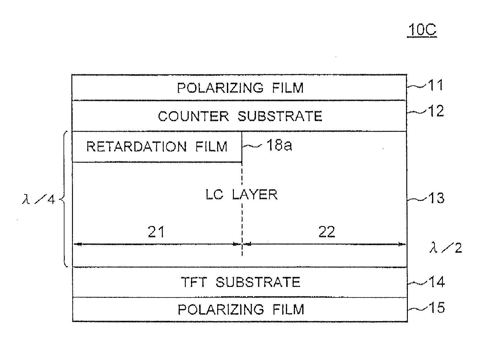
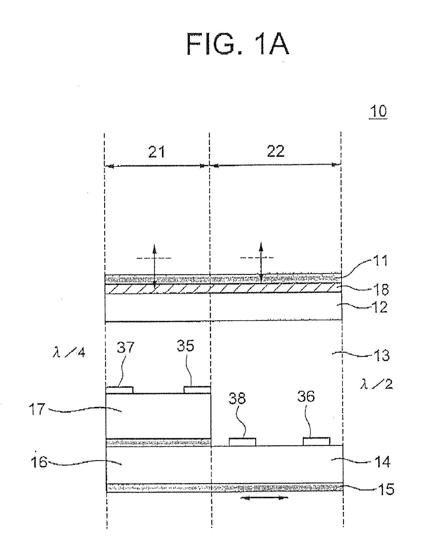
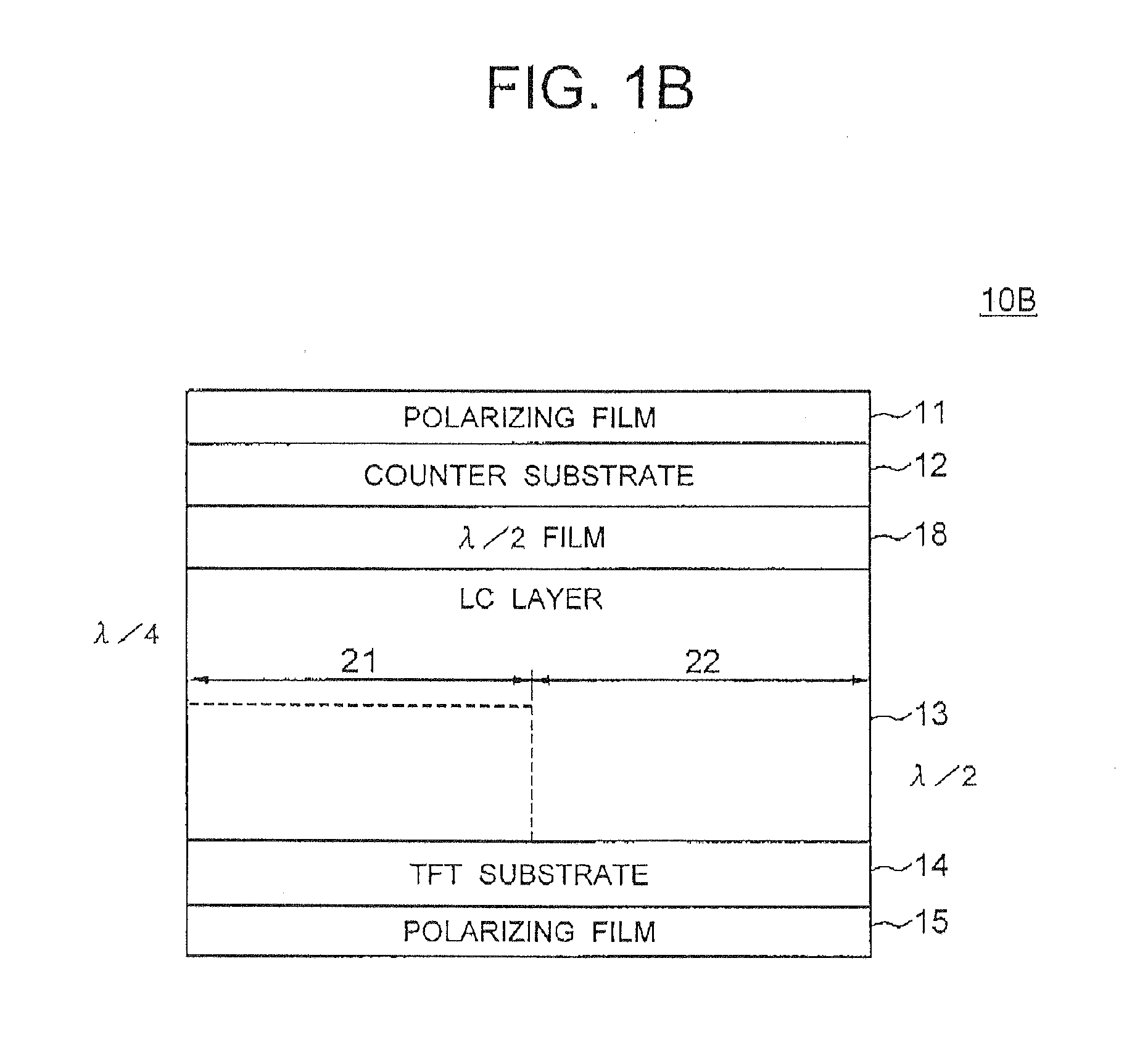
[0053]Embodiments of the present invention will be described below in detail with reference to the accompanying drawings. FIG. 1A shows the sectional structure of a LCD device according to a first embodiment of the present invention. The LCD device, generally designated at numeral 10, includes a first polarizing film 11, a first λ / 2 film 18, a counter substrate 12, a LC layer 13, a TFT substrate 14, a second λ / 2 film 19, and a second polarizing film 15, which are consecutively layered from the front side of the LCD device 10.

[0054]The LCD device 10 is configured as a transflective LCD device having a reflective area 21 and a transmissive area 22 in each pixel of the LCD device 10. In the reflective area 21, a reflection film 16 and an insulating film 17 are formed on the TFT substrate 14. The reflection film 16 reflects the incident light incident through the first polarizing film 11. In order to enhance light dispersion effect, the reflection film 16 typically has a rough surface.

[...


PUM

PropertyMeasurementUnit
wavelengthaaaaaaaaaa
angleaaaaaaaaaa
wavelengthaaaaaaaaaa

Abstract

A LCD device has a LC layer sandwiched between a TFT substrate and a counter substrate, first and second polarizing films, a first λ / 2 film between the first polarizing film and the counter substrate, and a second λ / 2 film between the second polarizing film and the TFT substrate. Angle θ1 between the direction of the optical axis of the LC layer and the polarized direction of the light entering the LC layer satisfies the relationship: 0 degree<θ1<45 degrees. The resultant LCD device has lower leakage light and coloring.

Description

BACKGROUND OF THE INVENTION[0001]1. Field of the Invention[0002]The present invention relates to a transflective liquid-crystal-display (LCD) device and, more particularly, to a transflective LCD device having a transmissive area and a reflective area in each pixel of the LCD device.[0003]2. Description of the Related Art[0004]LCD devices are roughly categorized into two types including a transmissive LCD device and a reflective LCD device. In general, the transmissive LCD device has a backlight unit and controls the transmission amount of light from the backlight unit to thereby represent an image on the screen. The reflective LCD device has a reflection film that reflects light incident from the outside and uses the light reflected by the reflection film as a light source to represent an image. That is, the reflective LCD device does not require the backlight unit, and is more advantageous than the transmissive LCD device in terms of a reduction in power dissipation, thickness, an...

Claims


Application Information

Patent Timeline
Patent Type & Authority Applications(United States)
IPC IPC(8): G02F1/1335
CPCG02F1/133528G02F1/133555G02F1/13363G02F1/134363G09G3/3607G02F2001/133638G02F2413/03G02F2413/09G02F2001/133565G02F1/133565G02F1/133638G02F1/133631
Inventor NAGAI, HIROSHISAKAMOTO, MICHIAKIMORI, KENICHINAKA, KENICHIROUIKENO, HIDENORI
Owner NEC LCD TECH CORP
Why Eureka
Try Eureka