Optical compensation film for liquid crystal display and liquid crystal display including the same

Inactive Publication Date: 2015-09-17
TCL CHINA STAR OPTOELECTRONICS TECH CO LTD
View PDF7 Cites 2 Cited by
  • Summary
  • Abstract
  • Description
  • Claims
  • Application Information

AI Technical Summary

Benefits of technology

[0007]Aiming at improving the effect for reducing light leakage using a compensation film on a liquid crystal display, the present

Problems solved by technology

Generally, the insufficient dark state is a main factor limiting the contrast ratio of the liquid crystal display.
Thus it could be seen that when A-plate and C-plate compensation values in the prior

Method used


Image

  • Optical compensation film for liquid crystal display and liquid crystal display including the same
  • Optical compensation film for liquid crystal display and liquid crystal display including the same
  • Optical compensation film for liquid crystal display and liquid crystal display including the same

Examples


example 1

[0066]

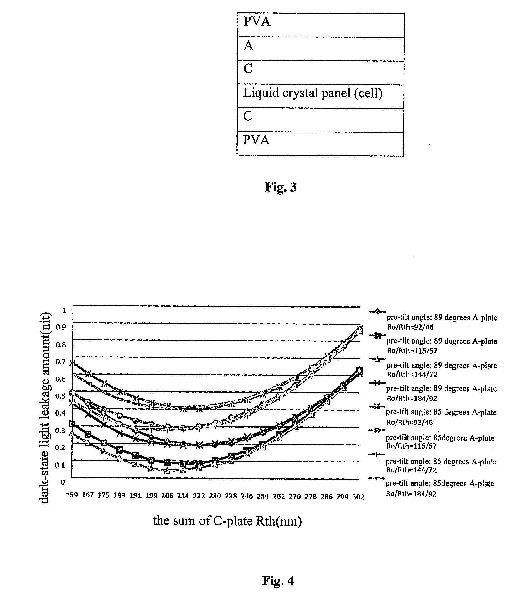
optical path differencepre-tilt angle ofA-plateA-platethe sum ofin liquid crystalliquid crystalRoRthC-plate Rth333.5 nm89 degrees132 nm66 nm179 nm

[0067]FIG. 6 shows a diagram of dark-state full-view light leakage distribution in Example 1, and FIG. 7 shows a diagram of full-view contrast distribution in Example 1.

example 2

[0068]

optical pathdifferencepre-tilt angle ofA-platethe sum ofin liquid crystalthe liquid crystalA-plate RoRthC-plate Rth333.5 nm89 degrees132 nm66 nm206 nm

[0069]FIG. 8 shows a diagram of dark-state full-view light leakage distribution in Example 2, and FIG. 9 shows a diagram of full-view contrast distribution in Example 2.

example 3

[0070]

optical pathdifferencepre-tilt angle ofA-platethe sum ofin liquid crystalthe liquid crystalA-plate RoRthC-plate Rth333.5 nm89 degrees132 nm66 nm266 nm

[0071]FIG. 10 shows a diagram of dark-state full-view light leakage distribution in Example 3, and FIG. 11 shows a diagram of full-view contrast distribution in Example 3.

[0072]In FIG. 6 to FIG. 11:

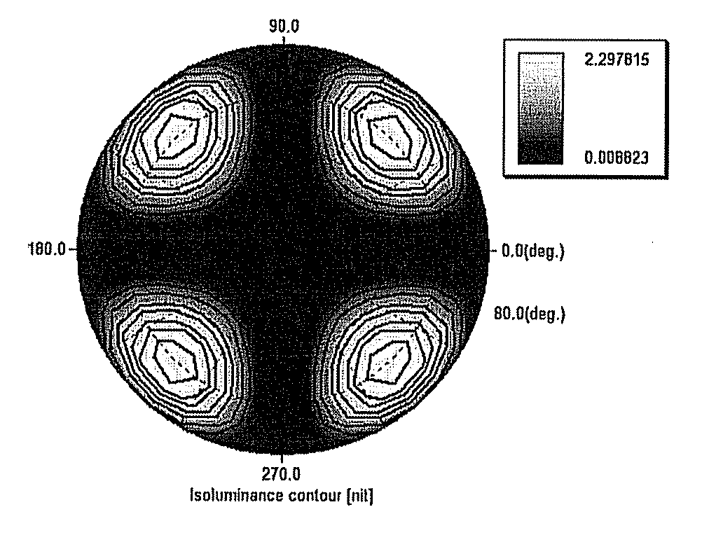
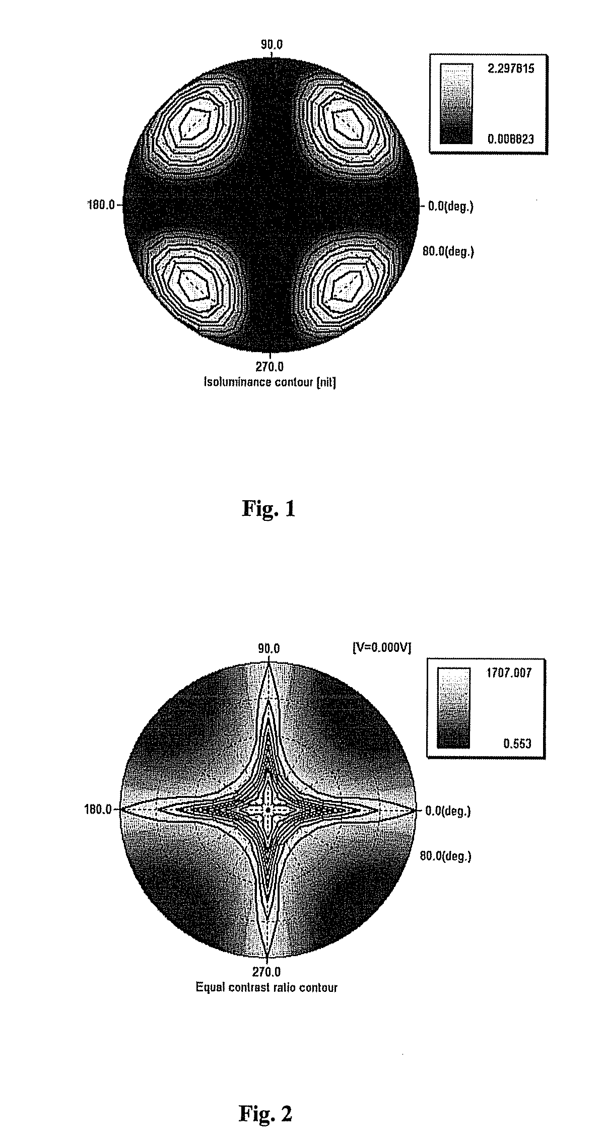
maximum lightminimum lightmaximumminimumleakage (nit)leakage (nit)contrastcontrastComparative2.2978150.0088231707.0070.553exampleExample 1:0.1877430.0077461715.62313.075Example 20.0505350.0085141707.92944.285Example 30.1940540.0088061742.3476.412

[0073]By comparing FIG. 6, FIG. 8 and FIG. 10 corresponding to Example 1, Example 2 and Example 3 respectively with FIG. 1, it could be found that after the compensation values of the A-plate and the C-plates of the optical compensation film are adjusted, the maximum dark-state light leakage is reduced from 2.3 nits to 0.2 nit or below, which is far lower than the dark-state light leakage obtai...


PUM


Abstract

The present invention relates to liquid crystal display technology, and provides an optical compensation film for a liquid crystal display, including a first C-plate arranged on one side of a liquid crystal panel, a first polarizer arranged outside the first C-plate, a second C-plate arranged on the other side of the liquid crystal panel, an A-plate arranged outside the second C-plate and a second polarizer arranged outside the A-plate, wherein the in-plane compensation value for optical path difference of the A-plate lies in the range of [92, 184] nm, and the compensation value for optical path difference in the thickness direction of the A-plate lies in the range of [46, 92] nm. The dark-state light leakage distribution and the contrast ratio of the display are improved through the optical compensation film according to the invention. The invention further provides a liquid crystal display including an optical compensation film.

Description

FIELD OF THE INVENTION[0001]The present disclosure relates to the technical field of liquid crystal display, and particularly, relates to an optical compensation film for a liquid crystal display and the liquid crystal display including the same.BACKGROUND OF THE INVENTION[0002]The contrast ratio of a liquid crystal display, directly related with its adaptability, significantly affects how it would be accepted by the market. The contrast ratio is a ratio of the luminance of the brightest color (white) to that of the darkest color (black) of the display. Generally, the insufficient dark state is a main factor limiting the contrast ratio of the liquid crystal display. With the increase of a viewing angle of a thin film transistor-liquid crystal display (TFT-LCD), the contrast ratio of pictures is continually reduced, and the sharpness of the pictures also correspondingly declines. This is due to the fact that the birefringence of liquid crystal molecules in a liquid crystal layer is c...

Claims


Application Information

Patent Timeline
IPC IPC(8): G02B5/30G02F1/13363
CPCG02B5/3083G02F2413/11G02F1/133634G02F1/13363G02F2413/03G02F2413/06C09K2323/031B32B2457/202
Inventor KANG, CHIH-TSUNGHAI, BO
Owner TCL CHINA STAR OPTOELECTRONICS TECH CO LTD
Why Eureka
Try Eureka