Lens driving apparatus with Anti-shake mechanism

a technology of anti-shake mechanism and lens driving apparatus, which is applied in the direction of printers, instruments, camera focusing arrangement, etc., can solve the problems of displacement that cannot be compensated by the lens driving apparatus's auto focusing or zooming capability, and the lens cannot be moved along the optical axis to achieve the auto focus or zooming function

Inactive Publication Date: 2010-12-30
HON HAI PRECISION IND CO LTD
View PDF7 Cites 20 Cited by
  • Summary
  • Abstract
  • Description
  • Claims
  • Application Information

AI Technical Summary

Benefits of technology

[0005]A typical voice coil motor includes a hollow core member with a coil of wire wound around it, and a plurality of magnets fixed adjacent to the hollow core member. A lens or a lens module can be received in the core member. When the coil of wire is electrified, magnetic fields generated by the magnets are able to drive the coil of wire together with the core member to move along an optical axis of the lens.

Problems solved by technology

However, with the above-mentioned lens driving apparatus, the lens can only be moved along the optical axis to achieve the auto focus or zooming function.
The camera module may be inadvertently displaced (e.g. shaken) during use, with displacement of the lens occurring in transverse directions perpendicular to the optical axis.
Such displacement cannot be compensated by the lens driving apparatus's auto focusing or zooming capability.
As a result, the image formed on an image sensor of the camera module may be blurred.

Method used


Image

  • Lens driving apparatus with Anti-shake mechanism
  • Lens driving apparatus with Anti-shake mechanism
  • Lens driving apparatus with Anti-shake mechanism

Examples


first embodiment

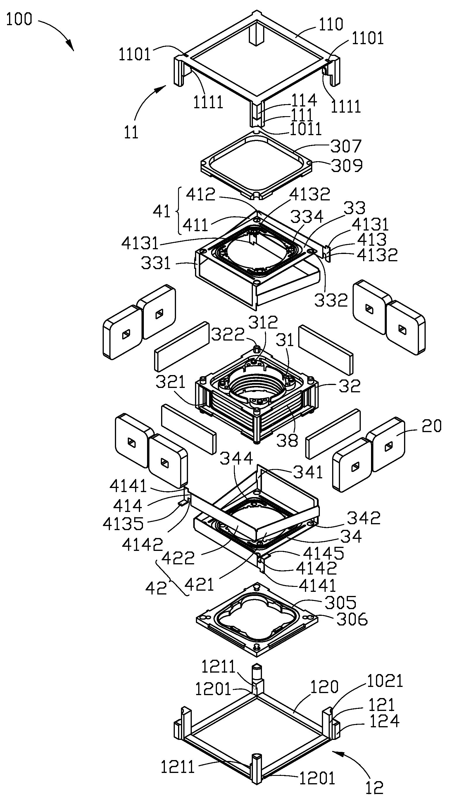
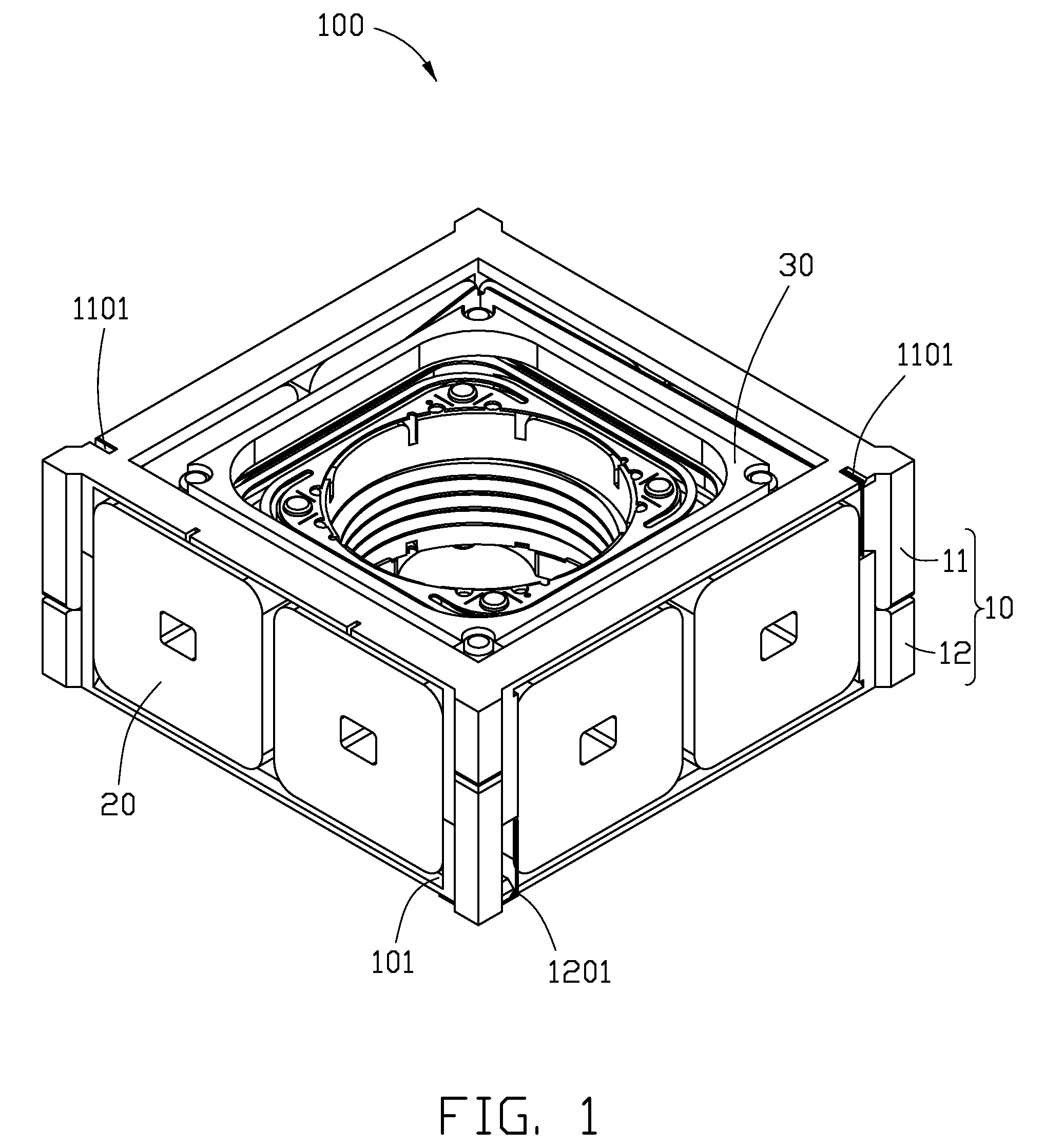
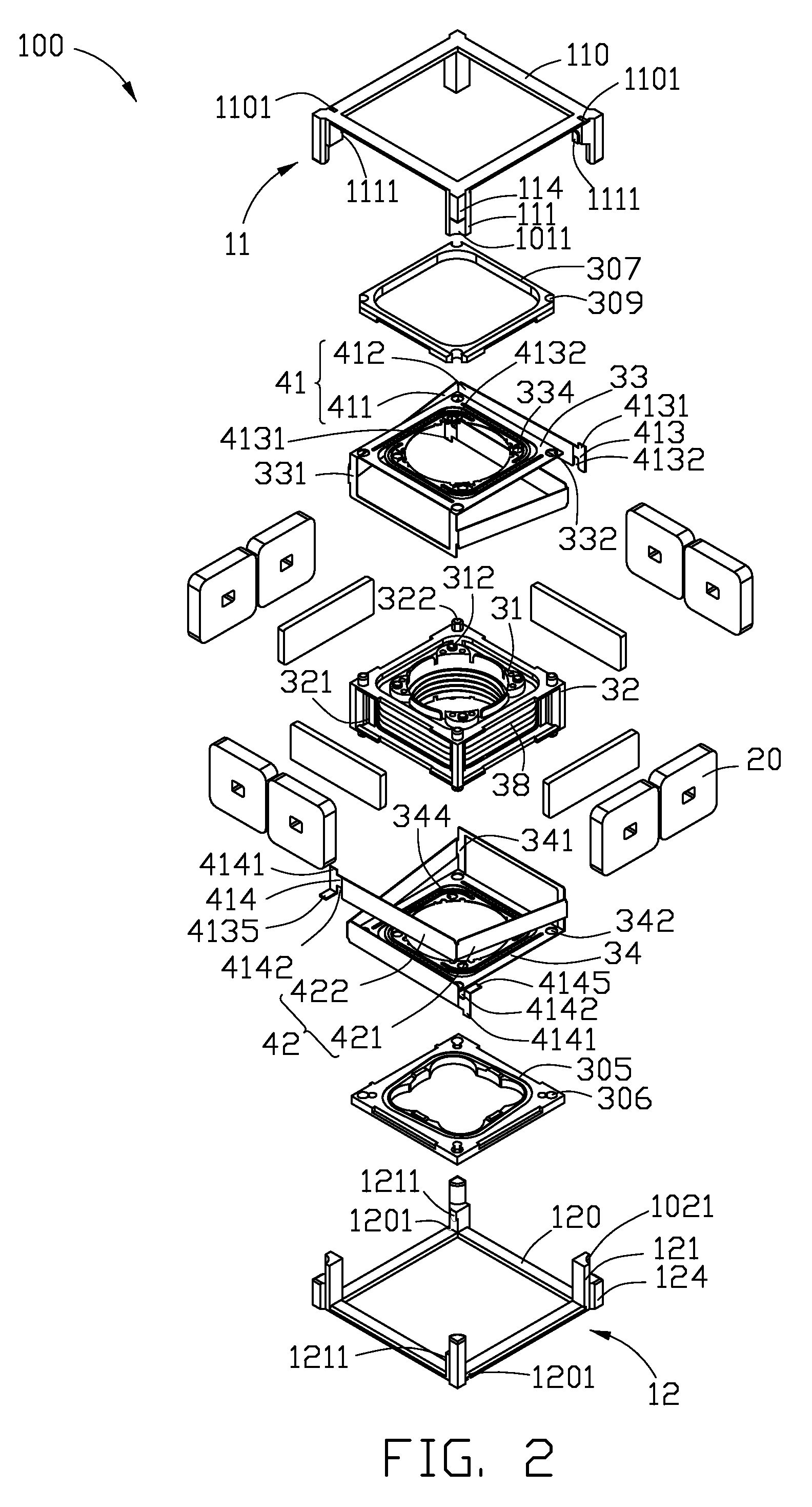
[0017]Referring to FIGS. 1 to 4, a lens driving apparatus 100 in accordance with a first embodiment is shown. The lens driving apparatus 100 mainly includes a hollow first retaining frame 10, a plurality of first coils of wire 20 mounted at sides of the first retaining frame 10, a voice coil motor 30, two first elastic members 41, and two second elastic members 42. The voice coil motor 30 is suspended and movably received in the first retaining frame 10 by the first and second elastic members 41, 42. Space 36 (see FIG. 3) is maintained between the voice coil motor 30 and the first retaining frame 10 having the first coils of wire 20, to facilitate free movement of the voice coil motor 30 in the first retaining frame 10.

[0018]The first retaining frame 10 includes an upper portion 11 and a lower portion 12. The upper portion 11 includes four top horizontal beams 110, four first vertical beams 111, and four second vertical beams 114 adjoining the four first vertical beams 111, respecti...

second embodiment

[0031]Referring to FIG. 5, a lens driving apparatus 200 in accordance with a second embodiment is shown. In the lens driving apparatus 200, a first retaining frame 201 and a second retaining frame 232 are similar to the first retaining frame 10 and the second retaining frame 32 of the lens driving apparatus 100. However, the first retaining frame 201 is a single body of material integrally formed. That is, the first retaining frame 201 is a one-piece body. The first retaining frame 201 has a plurality of protrusions 202 formed on vertical beams thereof. Two elastic members 203 are directly provided between the first retaining frame 201 and the second retaining frame 232. The elastic members 203 each include a first beam 204, and a second beam 205 bent relative to the first beam 204. First ends of the first beam 204 of each elastic member 203 are mounted to the second retaining frame 232. Second ends of the second beam 205 of each elastic member 203 each have a through hole 206 defin...

third embodiment

[0032]Referring to FIG. 6, a plurality of elastic members 392 of a lens driving apparatus 300 in accordance with a third embodiment are shown. Each of the elastic members 392 has an elongated strip shape. In the present embodiment, each of the elastic members 392 is an elongated plate, with opposite lateral edges of the plate being at opposite top and bottom ends of a voice coil motor (not shown). First ends of the elastic members 392 are connected to a second retaining frame 382 of the voice coil motor. Second ends of the elastic members 392 each have a through hole 301 defined therein. Each through hole 301 can engagingly receive a corresponding protrusion formed on a first retaining frame (not shown). An acute angle θ is maintained between each of the elastic members 392 and a corresponding side surface of the second retaining frame 382. In the present embodiment, each elastic member 392 is oriented in substantially the same horizontal plane that the second retaining frame 382 is...


PUM


Abstract

An exemplary lens driving apparatus includes a first retaining frame having first retaining portions, first coils of wire received in the first retaining portions, and a voice coil motor movably received in the first retaining frame. The voice coil motor includes a second retaining frame having second retaining portions, magnets received in the second retaining portions, and a core member having a second coil of wire wound around and being movably received in the second frame. The core member receives lens therein. The magnets generate magnetic fields which are capable of driving the core member to move along the lens optical axis when the second coil of wire is electrically powered; the magnets are applied reverse force of Ampere's force when the first coils of wire are electrically powered, such that the voice coil motor together with the lens is moved in a plane perpendicular to the lens optical axis.

Description

BACKGROUND[0001]1. Technical Field[0002]The present disclosure relates to lens driving apparatuses, and particularly, to a lens driving apparatus having an anti-shake mechanism.[0003]2. Description of Related Art[0004]A driving apparatus in a camera module is used to drive a lens to move and thereby provide an auto focus function or a zooming function. A common type of driving apparatus is the voice coil motor (VCM).[0005]A typical voice coil motor includes a hollow core member with a coil of wire wound around it, and a plurality of magnets fixed adjacent to the hollow core member. A lens or a lens module can be received in the core member. When the coil of wire is electrified, magnetic fields generated by the magnets are able to drive the coil of wire together with the core member to move along an optical axis of the lens.[0006]However, with the above-mentioned lens driving apparatus, the lens can only be moved along the optical axis to achieve the auto focus or zooming function. T...

Claims


Application Information

Patent Timeline
Patent Type & Authority Applications(United States)
IPC IPC(8): G03B17/00G03B13/34G03B5/00G03B30/00
CPCG03B13/34H02K2201/18H02K41/0354G03B17/00
Inventor CHIANG, SHUN-FAN
Owner HON HAI PRECISION IND CO LTD
Why Eureka
Try Eureka