Heat engine with nozzle

a technology of heat engine and nozzle, which is applied in the direction of combustion control, lighting and heating apparatus, domestic stoves or ranges, etc., can solve the problems of device and certain components thereof having various limitations and disadvantages

Inactive Publication Date: 2010-12-30
DENG DAVID
View PDF107 Cites 39 Cited by
  • Summary
  • Abstract
  • Description
  • Claims
  • Application Information

AI Technical Summary

Benefits of technology

[0008]Some embodiments can further comprise an outlet valve. The outlet valve can be configured to direct a flow of fuel to either the first flow configuration or the second flow configuration of the burner nozzle, the outlet valve can also be configured to direct a flow of fuel to either a first ODS channel or a second ODS channel. The fuel selector valve can have a first flow configuration and a second flow configuration therethrough and the first position of the fuel selector valve can correspond to the first flow configuration through the fuel selector valve, the first flow configuration of the burner nozzle and can configure the outlet valve to direct flow to the first ODS channel and the second position of the fuel selector valve can correspond to the second flow configuration through the fuel selector valve, the second flow configuration of the burner nozzle and can configure the outlet valve to direct flow to the second ODS channel. Some embodiments can further comprise a control valve. The fuel selector valve can be configured to direct a flow of fuel to the control valve and the control valve can be configured to direct a flow of fuel to the outlet valve, the control valve can also control an amount of flow through the heat engine.
[0009]A burner nozzle can have a first orifice and a second orifice wherein the second orifice can be smaller than the first orifice and a first flow configuration through the burner nozzle passes through both the first and second orifices and a second flow configuration passes through only one of the orifices. The burner nozzle can define an outlet end and the second orifice can be spaced from the outlet end of the burner nozzle where the first orifice is at the outlet end of the burner nozzle. In the second flow configuration, gas can be permitted to flow through the first orifice but not the second orifice.
[0010]A heat engine for use with one of a first fuel and a second fuel can comprise a fuel selector valve having a first position permitting flow of the first fuel and preventing flow of the second fuel and a second position permitting flow of the second fuel and preventing flow of the first fuel and a burner nozzle forming a single unit with the fuel selector valve and having a first flow configuration corresponding to the first fuel and a second flow configuration corresponding to the second fuel.

Problems solved by technology

However, such devices and certain components thereof have various limitations and disadvantages.

Method used


Image

  • Heat engine with nozzle
  • Heat engine with nozzle
  • Heat engine with nozzle

Examples


Embodiment Construction

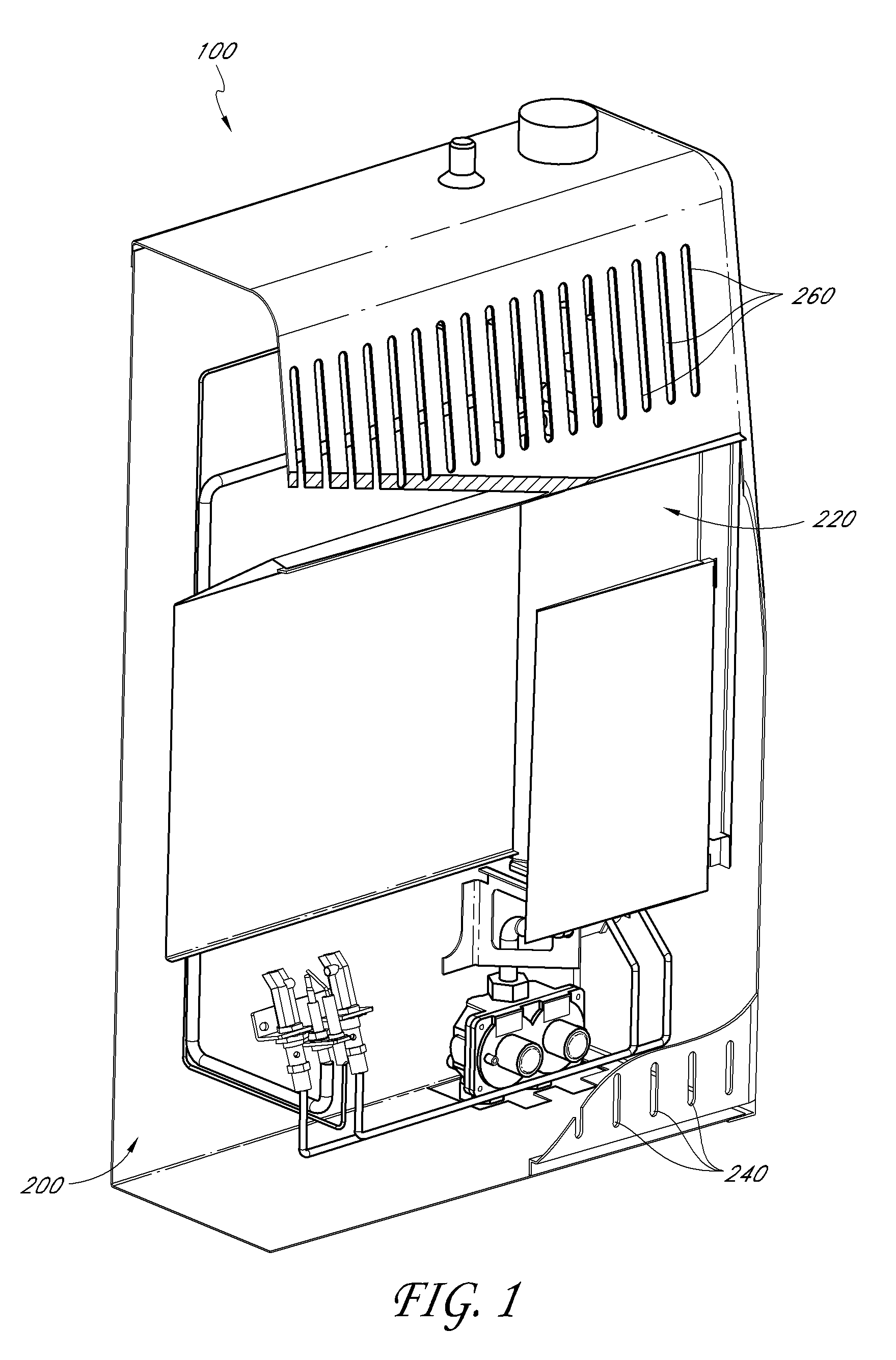
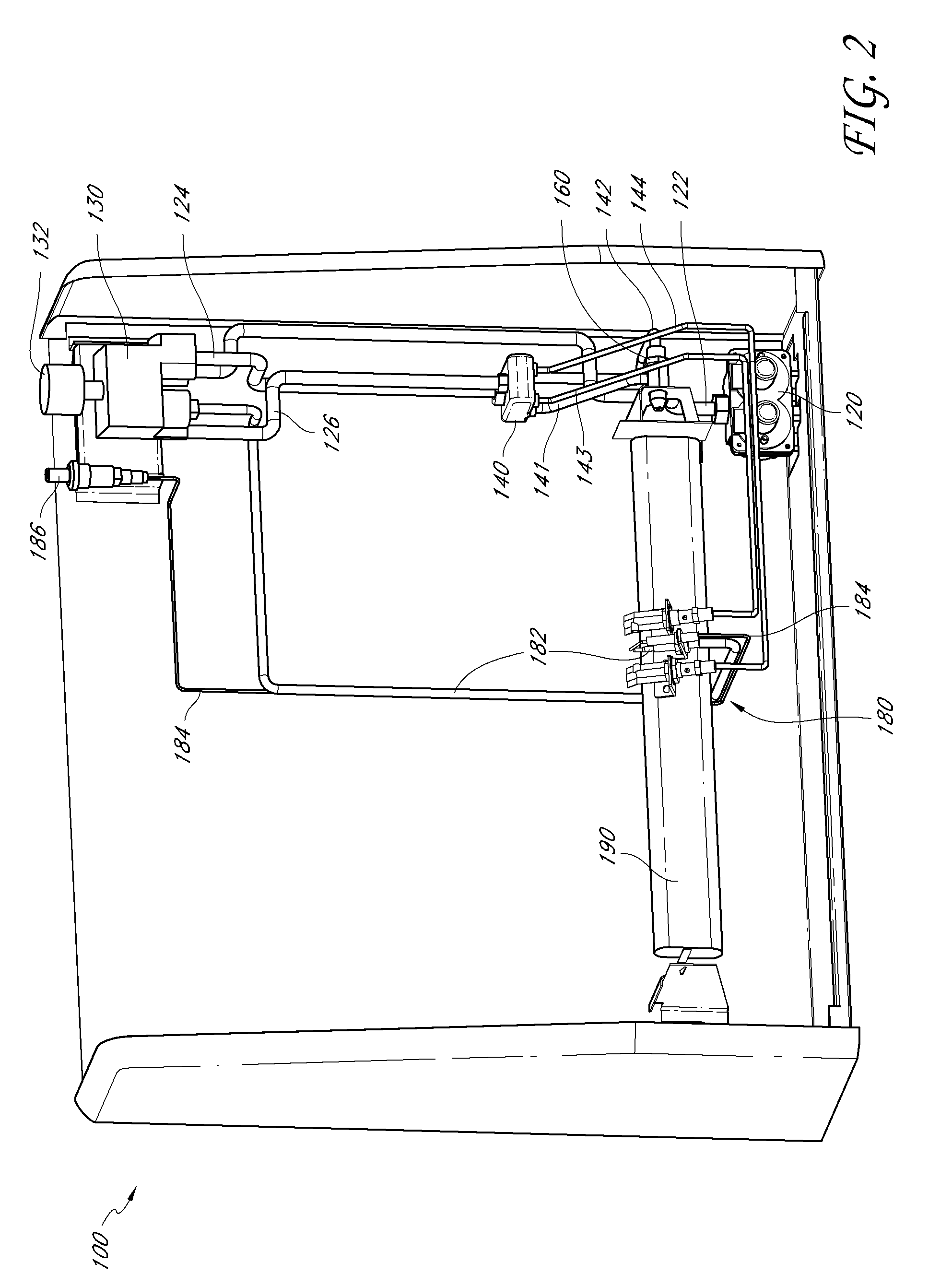
[0067]Many varieties of space heaters, fireplaces, stoves, ovens, boilers, fireplace inserts, gas logs, and other heat-producing devices employ combustible fuels, such as liquid propane and natural gas. These devices generally are designed to operate with a single fuel type at a specific pressure. For example, as one having skill in the art would appreciate, some gas heaters that are configured to be installed on a wall or a floor operate with natural gas at a pressure in a range from about 3 inches of water column to about 6 inches of water column, while others operate with liquid propane at a pressure in a range from about 8 inches of water column to about 12 inches of water column.

[0068]In many instances, the operability of such devices with only a single fuel source is disadvantageous for distributors, retailers, and / or consumers. For example, retail stores often try to predict the demand for natural gas units versus liquid propane units over a given season, and accordingly stoc...


PUM


Abstract

A heat engine can have a fuel selector valve for selecting between a first fuel and a second fuel. Making the selection with the fuel selector valve can also determine a flow path through the heat engine, there being two different paths, each configured for a different fuel. A burner nozzle can form a single unit with the fuel selector valve. In some embodiments the burner nozzle can also form a single unit with an outlet valve.

Description

CROSS-REFERENCE TO RELATED APPLICATIONS[0001]This application claims priority to U.S. Provisional Application Nos.: (1) 61 / 221,521, filed Jun. 29, 2009; (2) 61 / 221,520, filed Jun. 29, 2009; (3) 61 / 221,529, filed Jun. 29, 2009; (4) 61 / 221,528, filed Jun. 29, 2009; (5) 61 / 287,147, filed Dec. 16, 2009; (6) 61 / 286,355, filed Dec. 14, 2009; (7) 61 / 286,354, filed Dec. 14, 2009; (8) 61 / 286,352, filed Dec. 14, 2009; and (9) 61 / 304,373, filed Feb. 12, 2010; the entire contents of all of which are hereby incorporated by reference herein and made a part of this specification. The following U.S. patent application Nos. are also incorporated by reference herein and made a part of this specification: 11 / 443,484, filed May 30, 2006 (now U.S. Pat. No. 7,607,426); 11 / 443,446, filed May 30, 2006 (now U.S. Pat. No. 7,677,236); 11 / 443,492, filed May 30, 2006 (now U.S. Pat. No. 7,434,447); 11 / 443,473, filed May 30, 2006; 11 / 649,976, filed Jan. 5, 2007; 12 / 047,206, filed Mar. 12, 2008; 12 / 047,156, filed ...

Claims


Application Information

Patent Timeline
Patent Type & Authority Applications(United States)
IPC IPC(8): F23D11/00F16K11/02F16K11/08
CPCF16K11/0836F23C1/08F23K5/005F23K5/06F24H3/006F23N2035/18F23N2037/02F23N2037/08F24C1/02F23N1/007Y10T137/86566Y10T137/86815Y10T137/87917Y10T137/86541Y10T137/86823Y10T137/87249Y10T137/86501Y10T137/87129Y10T137/87161Y10T137/86831F24H9/1881F23N2235/18F23N2237/08F23N2237/02
Inventor DENG, DAVID
Owner DENG DAVID
Why Eureka
Try Eureka