Fuel Nozzle Having a Swirl Duct and Method for Producing a Fuel Nozzle

a fuel nozzle and swirl technology, which is applied in the direction of combustion types, combustion processes, burners, etc., can solve the problems of complicated construction terms of nozzles, and achieve the effects of low cost, high flexibility in the selection of swirl-inducing geometry, and quick manufacturing

Inactive Publication Date: 2010-12-30
SIEMENS AG
View PDF24 Cites 6 Cited by
  • Summary
  • Abstract
  • Description
  • Claims
  • Application Information

AI Technical Summary

Benefits of technology

[0006]Within the framework of the inventive method for manufacturing a fuel nozzle at least one swirl duct is mounted in an outer jacket surface of a pin and / or in an inner surface of a sleeve. Subsequently the pin is attached in the sleeve so that the outer jacket surface of the pin is connected to the inner surface of the sleeve without completely sealing the duct when this is done. With the aid of the inventive method any swirl-inducing contours can be created flexibly and at low-cost.
[0021]Overall the inventive fuel nozzle can be manufactured quickly and at low cost, typically with the aid of the inventive method. It is characterized by a high flexibility in the selection of the swirl-inducing geometry and is flexible in its use.

Problems solved by technology

However such nozzles have a complicated layout in construction terms since the holes must be placed exactly.

Method used


Image

  • Fuel Nozzle Having a Swirl Duct and Method for Producing a Fuel Nozzle
  • Fuel Nozzle Having a Swirl Duct and Method for Producing a Fuel Nozzle
  • Fuel Nozzle Having a Swirl Duct and Method for Producing a Fuel Nozzle

Examples


Embodiment Construction

[0035]A first exemplary embodiment of the present invention will be explained in greater detail below with reference to FIGS. 1 through 7.

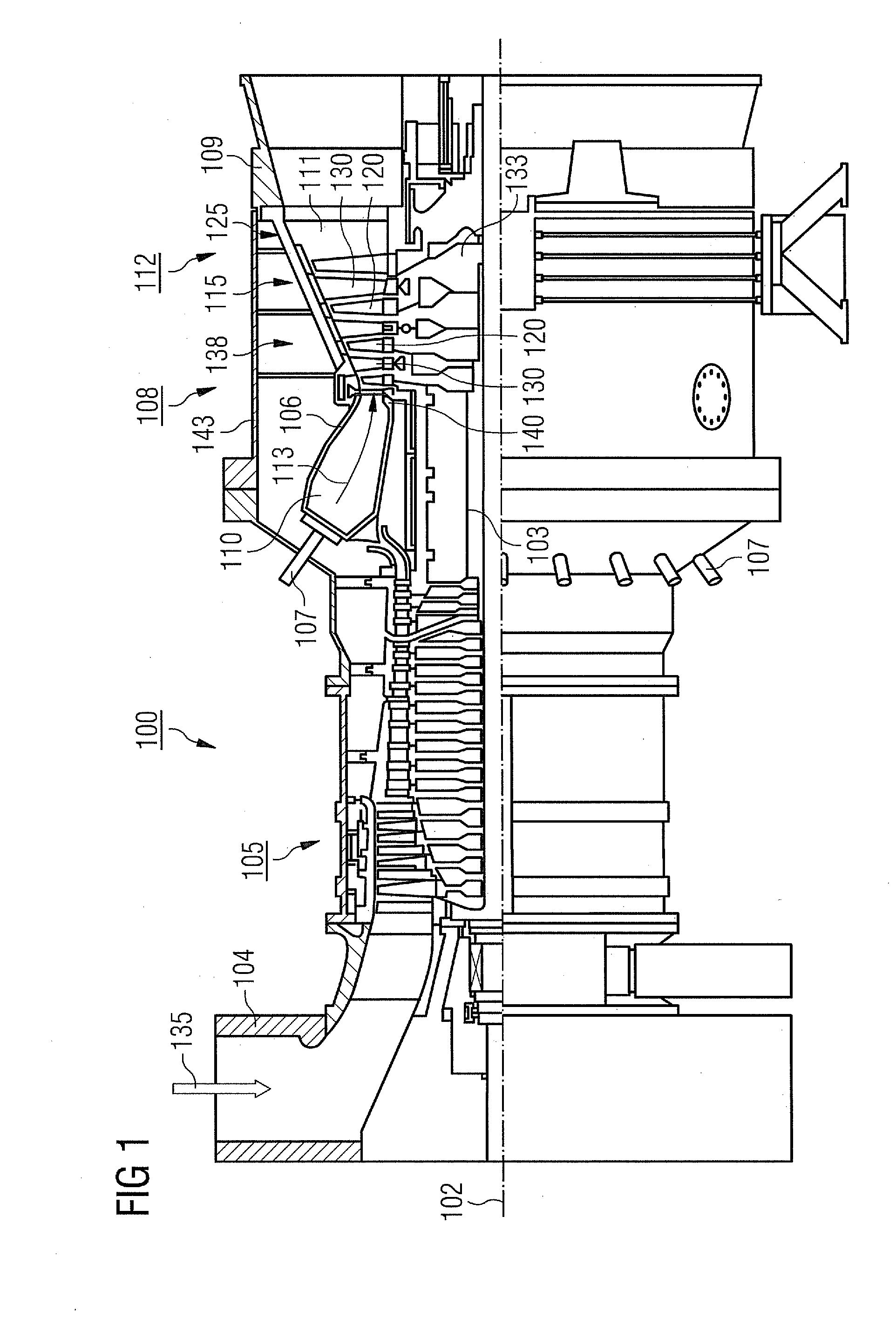
[0036]FIG. 1 shows an example of a gas turbine 100 in a longitudinal part section.

[0037]The gas turbine 100 has a rotor 103 inside it supported to allow its rotation around an axis of rotation 102 with a shaft, which is also referred to as the turbine rotor.

[0038]Following each other along the rotor 103 are an induction housing 104, a compressor 105, a typically toroidal combustion chamber 110, especially an annular combustion chamber, with a number of coaxially arranged burners 106, a turbine 107 and the exhaust housing 108.

[0039]The annular combustion chamber 110 communicates with a typically annular hot gas duct 111. In this duct four turbine stages 112 connected one behind the other form the turbine 108 for example.

[0040]Each turbine stage 112 is typically formed from two rings of blades. In the hot gas duct 111, seen in the flow direction of ...


PUM

PropertyMeasurementUnit
angleaaaaaaaaaa
angleaaaaaaaaaa
angleaaaaaaaaaa

Abstract

A method for producing a fuel nozzle is provided. In the method a swirl duct is mounted in an outer jacket surface of a pin and / or in an inner surface of a sleeve and the pin is attached in the sleeve so that the outer jacket surface of the pin is connected to the inner surface wherein the pin is disposed in the sleeve. The outer jacket surface of the pin and / or the inner surface of the sleeve includes at least one-swirl duct. A fuel nozzle and a burner are also further disclosed wherein the burner includes the fuel nozzle.

Description

CROSS REFERENCE TO RELATED APPLICATIONS[0001]This application is the US National Stage of International Application No. PCT / EP2008 / 065135, filed Nov. 7, 2008 and claims the benefit thereof. The International Application claims the benefits of European Patent Office application No. 08001641.3 EP filed Jan. 29, 2008. All of the applications are incorporated by reference herein in their entirety.FIELD OF INVENTION[0002]The present invention relates to a fuel nozzle with a swirl duct and to a method for manufacturing a fuel nozzle. The invention further relates to a burner and to a gas turbine.BACKGROUND OF INVENTION[0003]With combustion machines, especially such as are operated with two different fuels, oil as a fuel is typically injected via swirl ducts in which the oil is mixed with air. For improved mixing of oil and air a swirling movement is imparted to the oil within the nozzles used for injection. This swirl generation has previously been achieved by these nozzles consisting of ...

Claims


Application Information

Patent Timeline
Patent Type & Authority Applications(United States)
IPC IPC(8): F23D11/38B23P15/16B05B7/10
CPCF23D11/107Y10T29/49433
Inventor KRIEGER, TOBIASPFEIFFER, ELMAR
Owner SIEMENS AG
Why Eureka
Try Eureka