Trimmer Head For Use In Flexible Line Rotary Trimmers Having Improved Line Loading Mechanism

a technology of flexible line rotary trimmer and trimmer head, which is applied in the field of improved trimmer head, can solve the problems of time-consuming and common problems of the professional user in properly loading the line on the spool

Active Publication Date: 2011-01-06
PROULX MFG
View PDF6 Cites 46 Cited by
  • Summary
  • Abstract
  • Description
  • Claims
  • Application Information

AI Technical Summary

Benefits of technology

[0010]To provide an even winding and distribution of the protruding cutting line about the spool and prevent tangling within the spool during winding, a cam and cam follower mechanism is provided in the operative connection between the spool and housing to cause the spool to translate upwardly and downwardly with respect to the housing when the spool is gripped by the lower body portion of the spool and rotated in a given direction relative to the housing. This reciprocating movement of the rotating spool with respect to the housing provides for an even distribution of the cutting line about the spool as the line is wound thereon. To remove the line from the head, the user need only grip the exposed portion of the line in the open portion of the line receptor channel and pull that portion of the line in a direction away from the spool and substantially parallel to the axis of rotation of the spool, whereupon the line will simply unravel from the spool and separate from the head.
[0011]The present invention also can be utilized in rotary trimmer heads employing two separate lengths of cutting line. In such applications, the line receptor channel of the single line embodiment is effectively divided into two opposed channels. The two channels extend inwardly from opposed channel openings in the spool, and downwardly through opposed portions of the spool, exiting the spool at opposed outlet openings preferably adjacent to the outer surface of the body portion and above the lowermost end of the spool. Winding of the cutting lines onto the spool again is achieved by aligning the spool with the housing such that the open outer ends of the two opposed channels are radially aligned with the opposed eyelets or openings in the housing sidewall, directing a length of line through each of the openings in the housing wall and into an aligned receptor channel. The lines pass through portions of the spool and exit their respective channels adjacent or proximate the outer surface of the spool body and above the ground engaging or bumper surface at the lower end of the spool. Subsequent rotation of the spool relative to the housing while holding in place the end portions of the two lengths of cutting line protruding from the two channel outlet openings will effect the winding of the two lengths of line about the spool. To remove the line from the head, the user need only grip the exposed end portion of each line protruding from the channel outlet openings and pull both lengths of line in a direction away from the spool and substantially parallel to the axis of rotation of the spool, whereupon both lengths of line will simply unravel from the spool and separate from the head as in the single line embodiments of the present invention.

Problems solved by technology

Difficulty in properly loading the line on the spool is the most common complaint of home users of flexible line trimmers.
It also is a time consuming task for the professional user.
While these configurations do facilitate the loading of line onto the spool, they do not eliminate the need to remove the spool from the housing (known in the trade as splitting the head) in the event the cutting line breaks proximate the eyelet during use.
Unfortunately, this is a frequent occurrence when the rapidly rotating line strikes a solid object such as a fence post.

Method used


Image

  • Trimmer Head For Use In Flexible Line Rotary Trimmers Having Improved Line Loading Mechanism
  • Trimmer Head For Use In Flexible Line Rotary Trimmers Having Improved Line Loading Mechanism
  • Trimmer Head For Use In Flexible Line Rotary Trimmers Having Improved Line Loading Mechanism

Examples


first embodiment

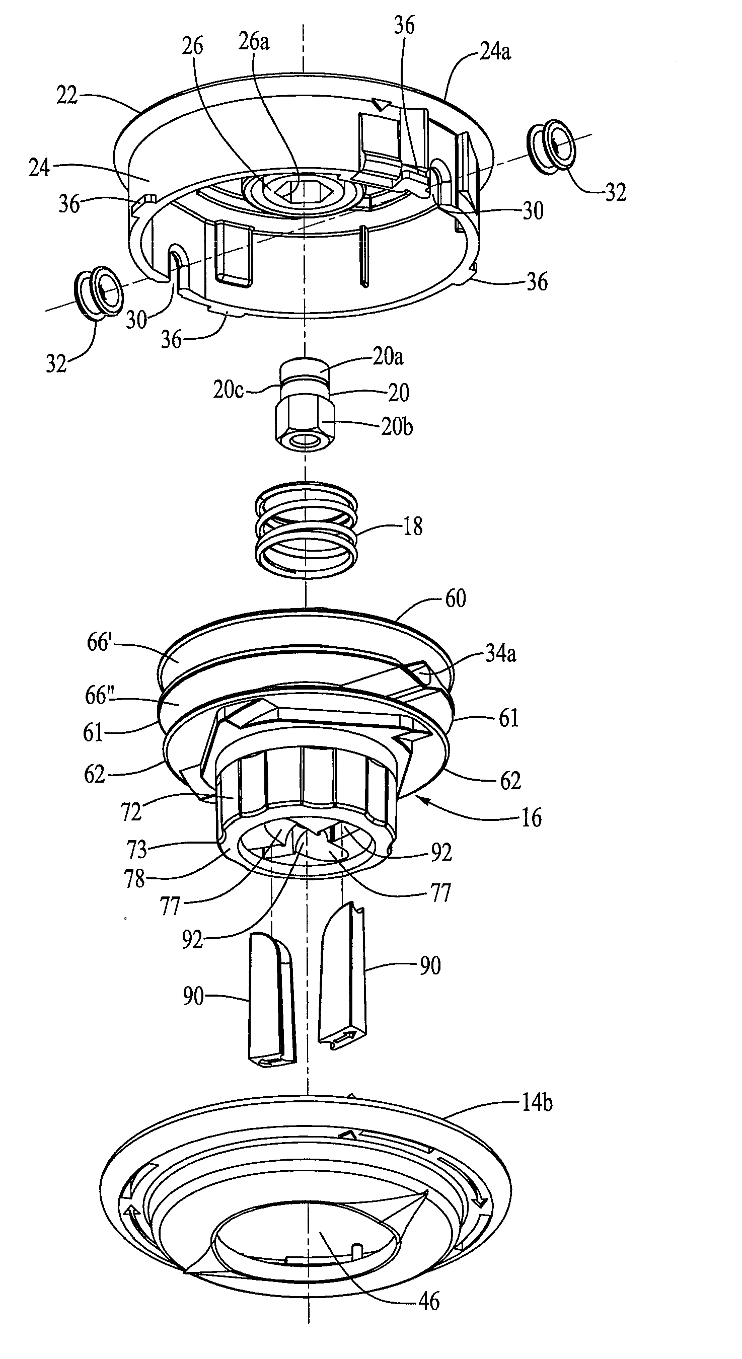
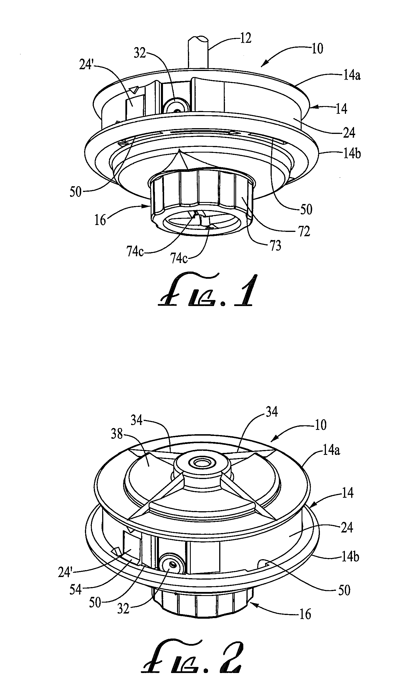
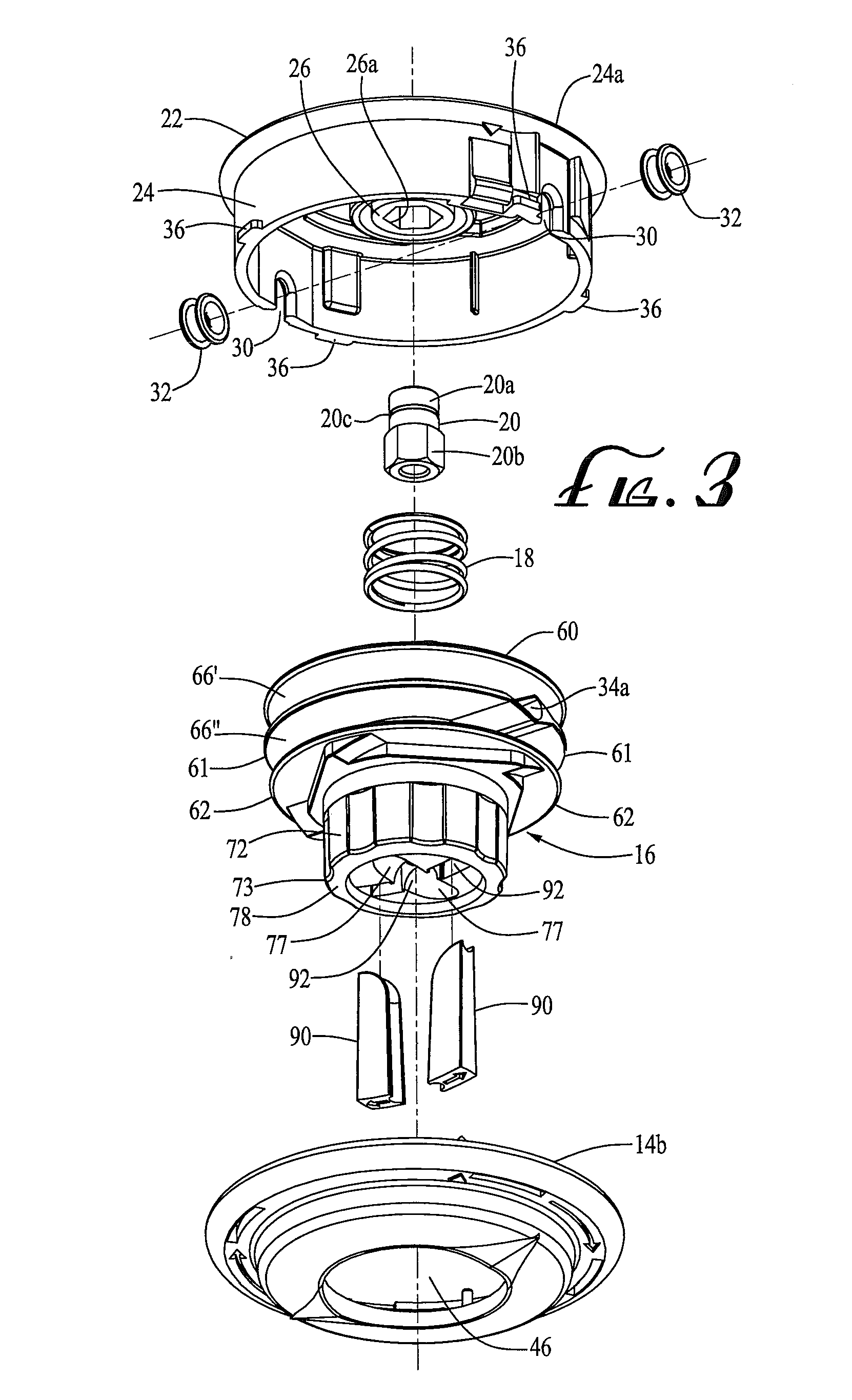
[0049]Referring now in detail to the drawings, a bump-feed type trimmer head 10 of the present invention is shown in FIGS. 1-15 and 20. The trimmer head 10 of the present invention shown therein is designed to be mounted on the extended end of a rotatable drive shaft 12 on a gasoline or electric powered rotary trimmer (not shown). The trimmer head 10 shown therein is a bump-feed type head having the drive and line feeding mechanism disclosed in U.S. Pat. No. 4,959,904 but including the rapid line loading and replacement feature of the present invention.

[0050]Trimmer head 10 comprises a housing 14, spool 16, coil spring 18 and drive bolt 20. The housing comprises an upper portion 14a and a lower portion 14b that are releasably secured together about the spool. The trimmer head housing and spool are preferably formed by injection molding a nylon 6 copolymer. The upper housing 14a defines an upper circular wall 22, a cylindrical housing skirt 24 depending therefrom and a centrally disp...

second embodiment

[0081]FIG. 23 illustrates the use of the present invention in a manual feed head similar to that disclosed in the above-referenced Publication No. U.S. 2005 / 0076515 A1 and illustrated in FIGS. 20-31 therein. In the manual feed head 410 shown in FIG. 23, the spool 416 is secured to the trimmer head housing 414 by a threaded nut 425 that threadably engages the drive bolt 424. The operative connection is defined by a plurality of drive lugs 421 extending upwardly from the upper surface of the upper flange 470 (only a portion of one lug being visible in FIG. 23), a corresponding plurality of lug receiving apertures 419 in the upper surface of the trimmer head housing 414. The drive lugs are held within the receiving apparatus by nut 425, compressing spring 422. As described in detail in the referenced published application, rotation of the trimmer head housing 414 by the drive bolt 424 is imparted to the spools via drive lugs 421.

[0082]The line receptor channel 474 in head 410 extends i...


PUM


Abstract

A trimmer head for a rotary line trimmer including a housing operatively connected to the trimmer and a spool for carrying cutting line thereon. The spool is operatively connected to the housing for rotation therewith and defines a pair of opposed line receptor channels having opposed open ends, traversing opposed portions of the spool and defining opposed outlet openings above a lowermost end of the spool. The channels can be aligned with the eyelets in the housing skirt such that lengths of cutting line can be inserted therethrough and wrapped about the spool upon relative rotation of the spool and housing without having to interrupt the operative connection therebetween. The channel outlet openings provide access to the inner ends of the line so that the line also can be pulled from the head without having to interrupt the operative connection therebetween.

Description

CROSS-REFERENCE TO RELATED APPLICATIONS[0001]This application is a continuation-in-part of application Ser. No. 12 / 032,633, filed Feb. 15, 2008, entitled “Trimmer Head for Use in Flexible Line Rotary Trimmers Having Improved Line Loading Mechanism” which is a continuation-in-part of application Ser. No. 11 / 833,085, having the same title and filed Aug. 2, 2007, which claims the benefit of U.S. Provisional Patent Application Ser. No. 60 / 824,404, filed Sep. 1, 2006, also entitled “Trimmer Head for Use in Flexible Line Rotary Trimmers Having Improved Line Loading Mechanism”.BACKGROUND OF THE INVENTION[0002]The present invention relates to an improved trimmer head for use in flexible line rotary trimming devices used to trim grass, weeds and other vegetation. More particularly, the invention is directed to an improvement in the line loading of both “bump-feed” type trimmer heads such as those disclosed in U.S. Pat. Nos. 4,458,419, 4,959,904 and 6,901,667 and the more simple manually oper...

Claims


Application Information

Patent Timeline
Patent Type & Authority Applications(United States)
IPC IPC(8): A01D34/416A01D34/73
CPCA01D34/4166A01D34/4165A01D34/4163
Inventor PROULX, RICHARD A.
Owner PROULX MFG
Why Eureka
Try Eureka