

Pneumatic Tire
- Summary
- Abstract
- Description
- Claims
- Application Information
AI Technical Summary
Benefits of technology
Problems solved by technology
Method used
Image

Examples
example
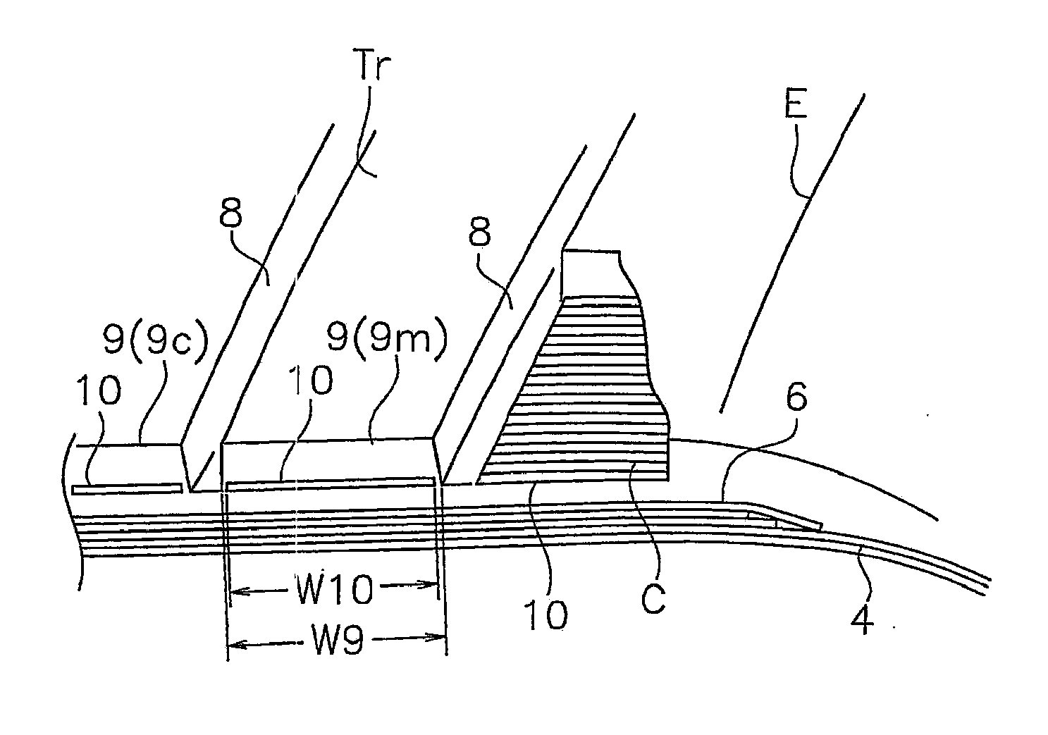
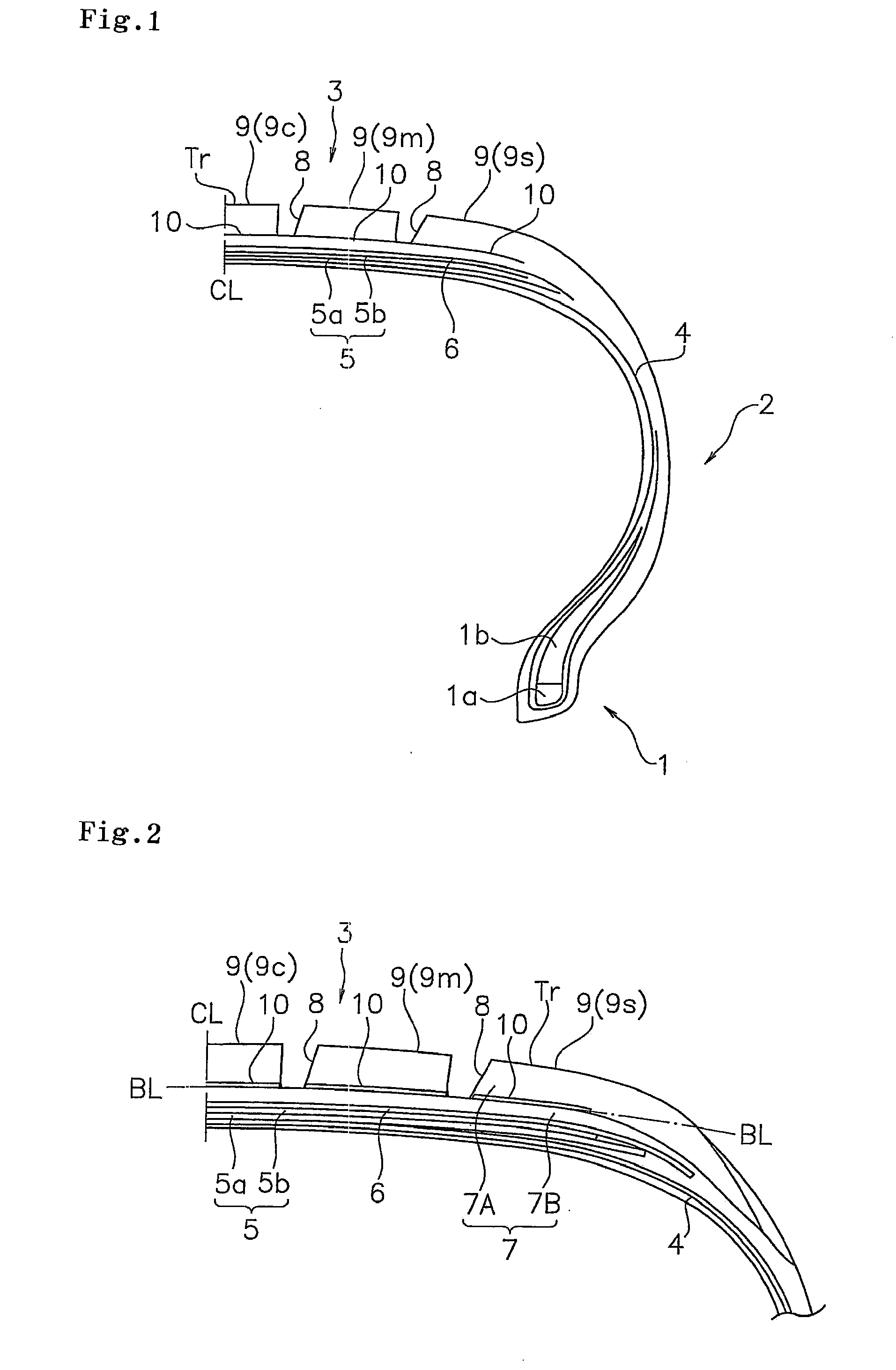
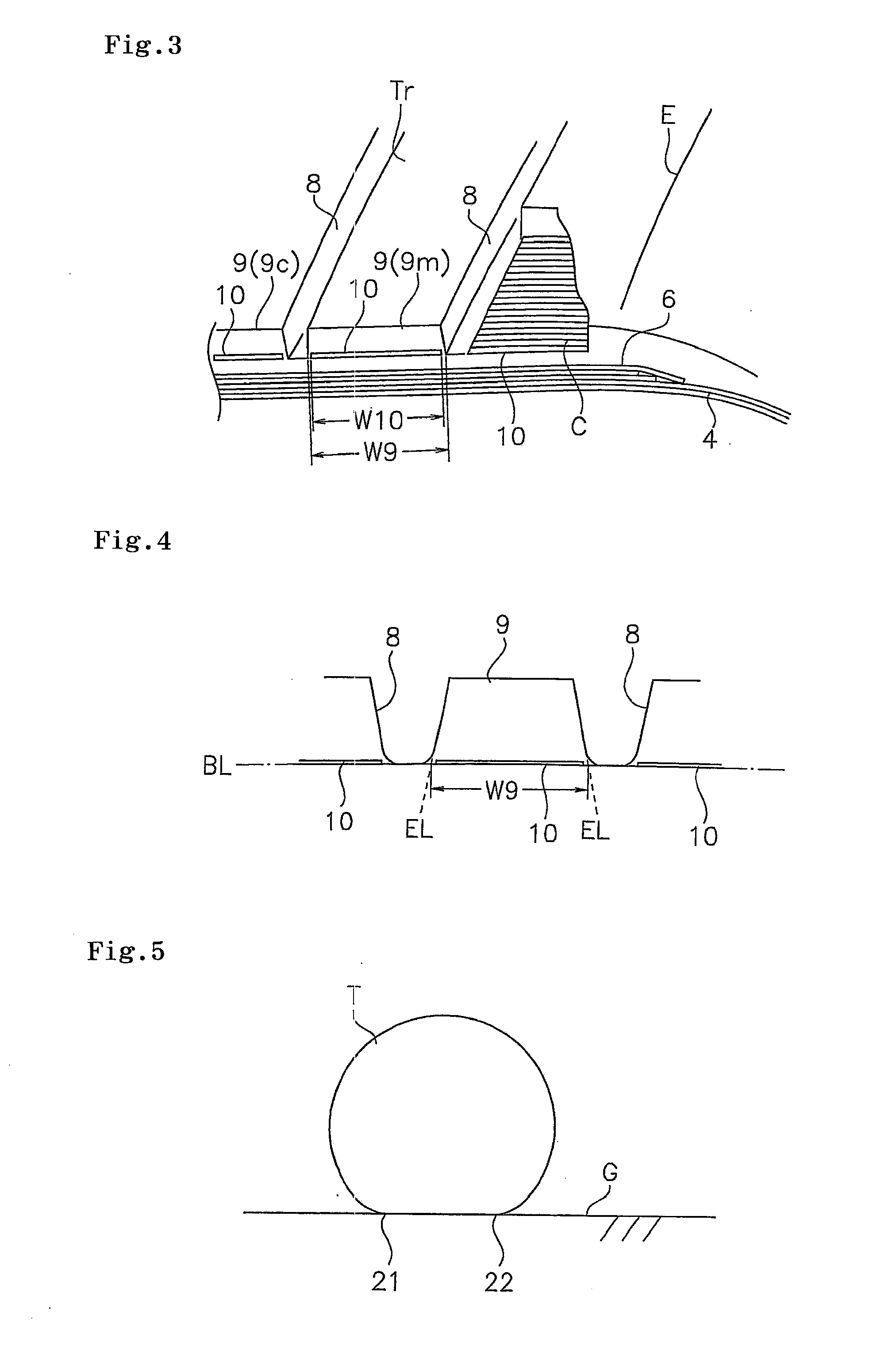
[0035]An example tire which concretely shows the structure and effect of the present invention will be explained. A measurement was carried out by setting evaluation items in the examples or the like as follows.
[0036](1) Rolling Resistance
[0037]The tire was assembled in a rim having a size 15×6.5JJ, an internal pressure 210 kPa thereafter was filled, a load 4.4 kN was set, and the rolling resistance was measured in accordance with US Society of Automotive Engineers SAE testing method J1269. A result of a comparative example 1 is set to 100 so as to be indexed, and the larger numerical value indicates the lower rolling resistance.
[0038](2) Steering Stability
[0039]The test tire was installed to the vehicle so as to execute a cornering travel, a braking and the like, and was evaluated in accordance with a subjective test of a driver. A result of the comparative example 1 is set to 100 so as to be indexed, and the larger numerical value indicates the more excellent steering stability.
[0...
PUM
 Abstract
Description
Claims
Application Information