
Method of pulling wire

a wire pulling and wire technology, applied in the direction of electric cable installation, overhead line/cable apparatus, electric cable suspension arrangement, etc., can solve the problems of lack of erosion resistance, and lack of the necessary stiffness characteristics to resist external influences, so as to reduce the effort involved in pulling and installing wiring, reduce the likelihood of being snagged or caught, and the effect of robustness, compactness and flexibility

Inactive Publication Date: 2011-01-06
SCUTARI ANTHONY +1
View PDF20 Cites 1 Cited by
  • Summary
  • Abstract
  • Description
  • Claims
  • Application Information

AI Technical Summary

Benefits of technology

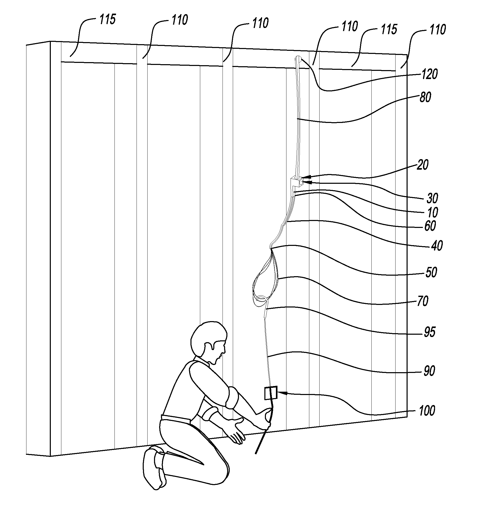
"The present invention is a wire installation device with a clamp and flexible loops. It is designed to be robust, compact, and flexible, and can be easily used by consumers or professionals. The device is ideal for use in spatially restricted or concealed areas, minimizing the effort involved in dragging and installing wiring. It is reliable, simple, and inexpensive to produce and market. It can support wire installations with or without conduits, ducts, or raceways. It can be fished out of a concealed space or used to snag and drag a separate fish line. It is capable of dragging and installing a section of wiring without any damage to the wire. The length of the device is adjustable."

Problems solved by technology

The core has great strength in tension but lacks the necessary resistance to erosion, the necessary stiffness characteristics and resistance to external influences and stresses to constitute a fish tape.

Method used


Image

  • Method of pulling wire
  • Method of pulling wire
  • Method of pulling wire

Examples


Embodiment Construction

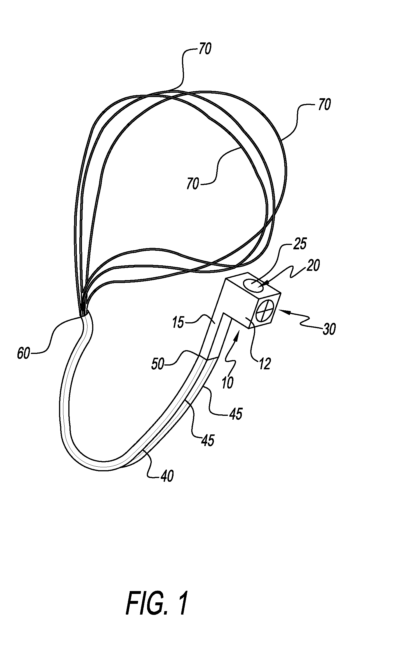
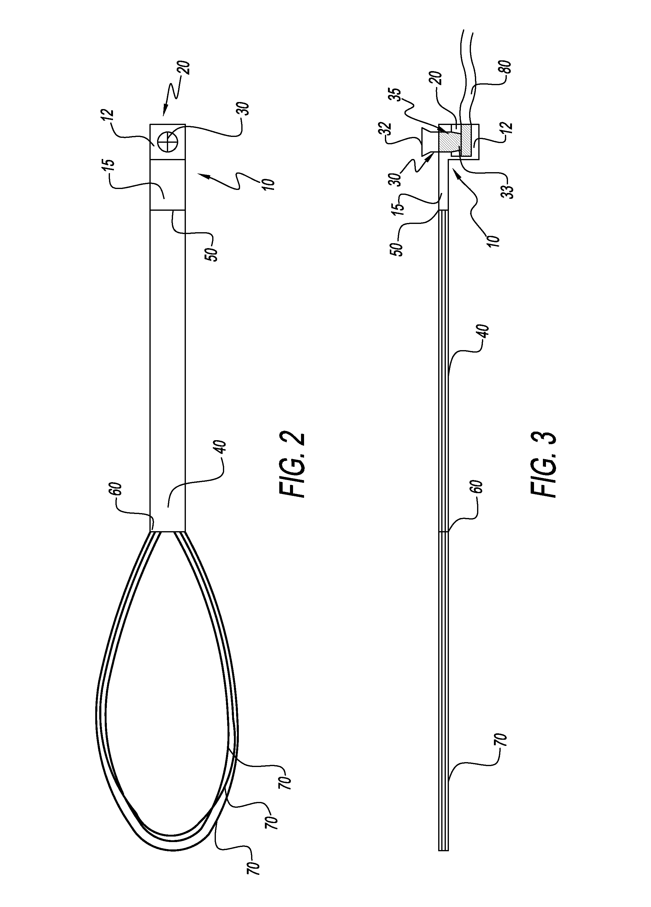
[0027]The preferred embodiments of the present invention will now be described with reference to the drawings. Identical elements in the various figures are identified with the same reference numerals.

[0028]Reference will now be made in detail to embodiment of the present invention. Such embodiments are provided by way of explanation of the present invention, which is not intended to be limited thereto. In fact, those of ordinary skill in the art may appreciate upon reading the present specification and viewing the present drawings that various modifications and variations can be made thereto.

[0029]FIG. 1 discloses a coiled up rendering of the present invention. Shown are a clamp 10, a lower section 12, an upper section 15, a hollow channel 20, a hollow channel opening 25, a set screw 30, a feeder 40, a rigid member 45, a first end 50, a second end 60, and a plurality of flexible loops 70. The ideal length of the present invention is between 10 inches and 3 feet. The clamp 10 is dis...


PUM


Abstract

The present invention relates to a wire installation device having a clamp and at least one flexible loop disposed on the clamp. The claimed device may also have a feeder section between the clamp and the loop. The loop or loops are preferably thin, and are capable of substantially dispersing from one another to increase the likelihood of being snagged or caught by a user's hand or a standard fish line. The loop or loops are flexible and made out of a tear resistant material. A set screw, or other tightening means, positioned on the clamp, securely holds the wire or cable that is being installed or threaded. The entire embodiment is designed to be robust, compact and flexible, and ideal for use within spatially restricted or concealed areas, to minimize the effort entailed in dragging and installing wiring. The present invention is a very flexible, inexpensive device that can be easily utilized by consumers or by those who are professionally engaged in the art.

Description

CLAIM OF PRIORITY[0001]This application claims the priority of U.S. Ser. No. 61 / 222,870 filed on Jul. 2, 2009, which is incorporated herein by reference.FIELD OF THE INVENTION[0002]The invention relates to a device for use in dragging and installing concealed wiring or cabling in residential and commercial structures.BACKGROUND OF THE INVENTION[0003]The invention relates to a unique and novel device that can be used to thread or drag a wire or cabling through cavities between beams and drywall or through conduits of various types. In the present state of the art, an assortment of means is being utilized for installing electrical conductors in conduits. The device most frequently employed in this pursuit is a metallic “fish tape” or “snake wire” which may be made from a flattened strip or spring steel material or may be formed of braided metal strands. In practice, such fish tapes or snake wires are pushed through a conduit preparatory to attaching either a guide line or an electrica...

Claims


Application Information

Patent Timeline
Patent Type & Authority Applications(United States)
IPC IPC(8): H02G1/08
CPCH02G1/081
Inventor SCUTARI, ANTHONYVICENDESE, FRANK
Owner SCUTARI ANTHONY
Learn More