Plow shovel

a shovel and shovel body technology, applied in the field of shovels, can solve the problems of inefficient performance, never made provision for relative adjustment of the handle and blade body, and inability to make provision for relative adjustment in the line of draft of the handle, so as to reduce the center of gravity of the angular setting and reduce the progressive resistance of the material moved

Inactive Publication Date: 2011-01-06
TOWLES HOWARD E
View PDF5 Cites 4 Cited by
  • Summary
  • Abstract
  • Description
  • Claims
  • Application Information

AI Technical Summary

Benefits of technology

[0027]These problems, including reducing the center of gravity of the angular settings, are solved by the duplex locking handle of this invention, by and including, but not limited to, reducing the progressive resistance of the material moved to the amount of inertial force necessary.

Problems solved by technology

However, to my knowledge, prior combination tools of this character have never made provision for relative adjustment of the handle and blade members in a manner by which the tool may be efficiently and comfortably operated in its respective capacities.
In prior art devices of which I am aware, the inner end of the handle member is usually secured to the rear side of the blade member so as to permit lateral pivotal or swinging movement of the handle relative to the blade or vice versa, in only one plane, thus failing to make any provision for relative adjustment in the line of draft of the handle such as is ordinarily required between snow shovels on the one hand and snow plows on the other.
In all such prior art of which I am aware, a resulting increase in the center of gravity of the fulcrum of various shovel blade settings causes inefficient performance due to unavoidable weight distribution and unavoidable stress during use.

Method used


Image

  • Plow shovel
  • Plow shovel
  • Plow shovel

Examples


Embodiment Construction

Item Number:

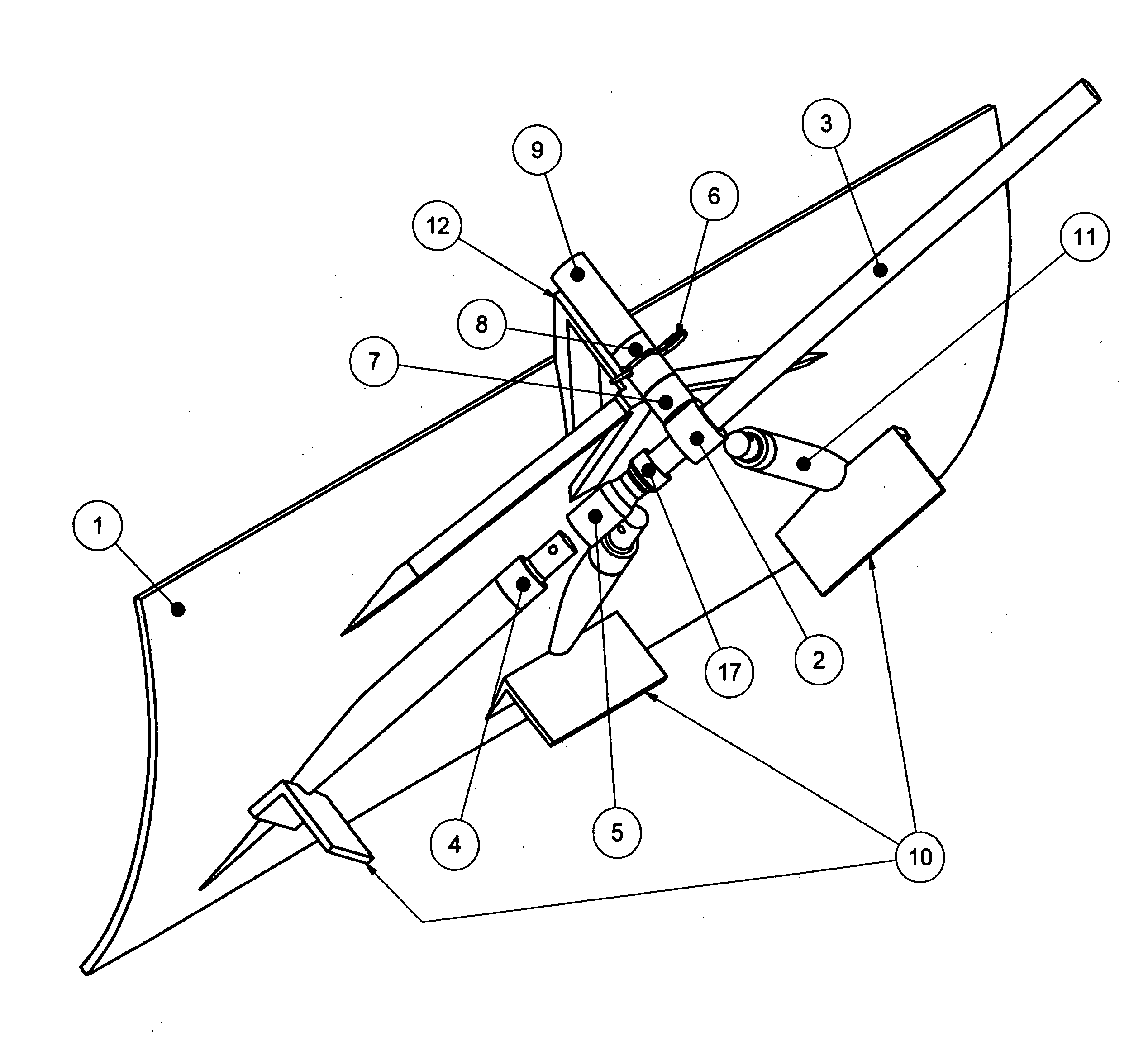
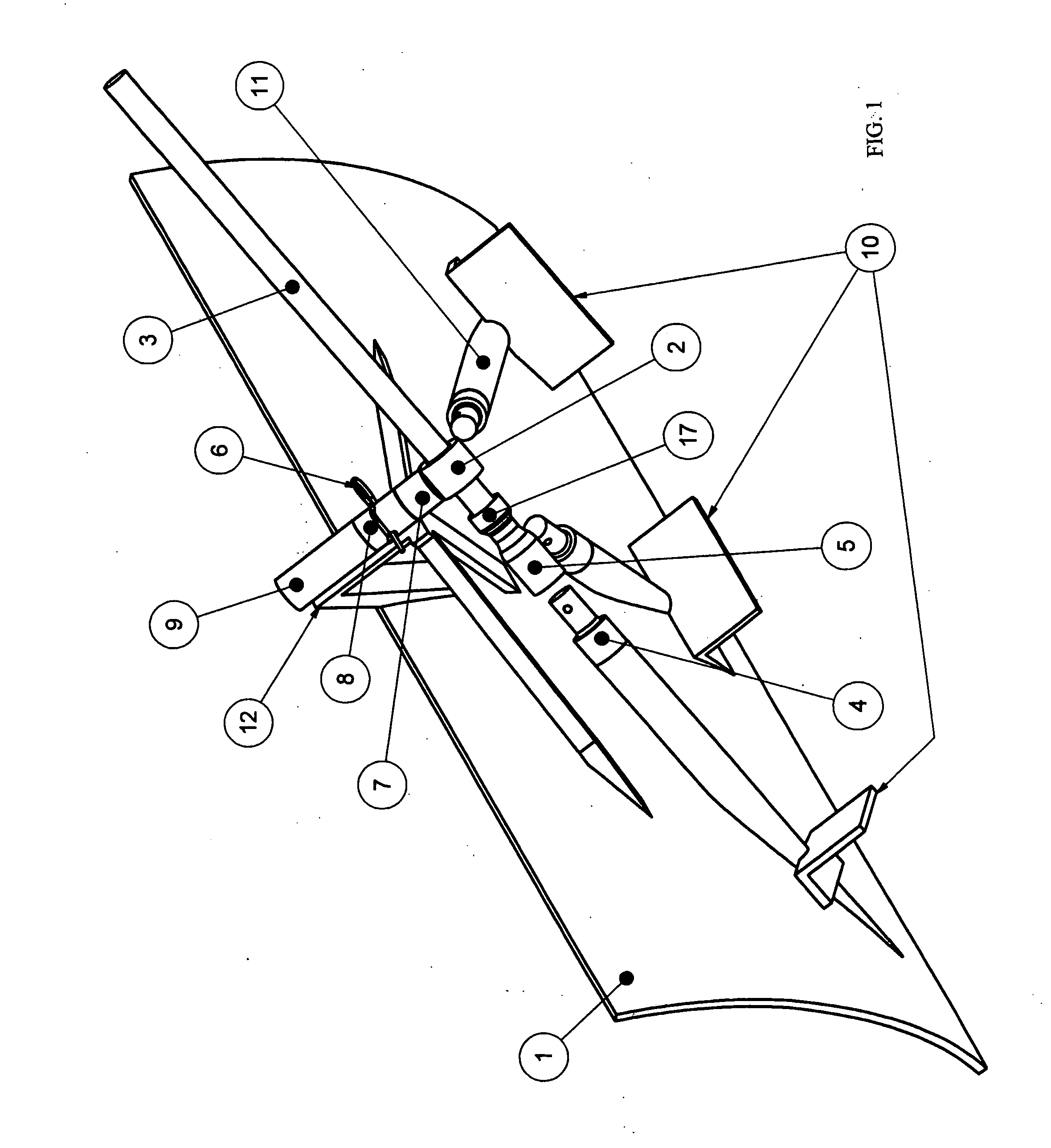
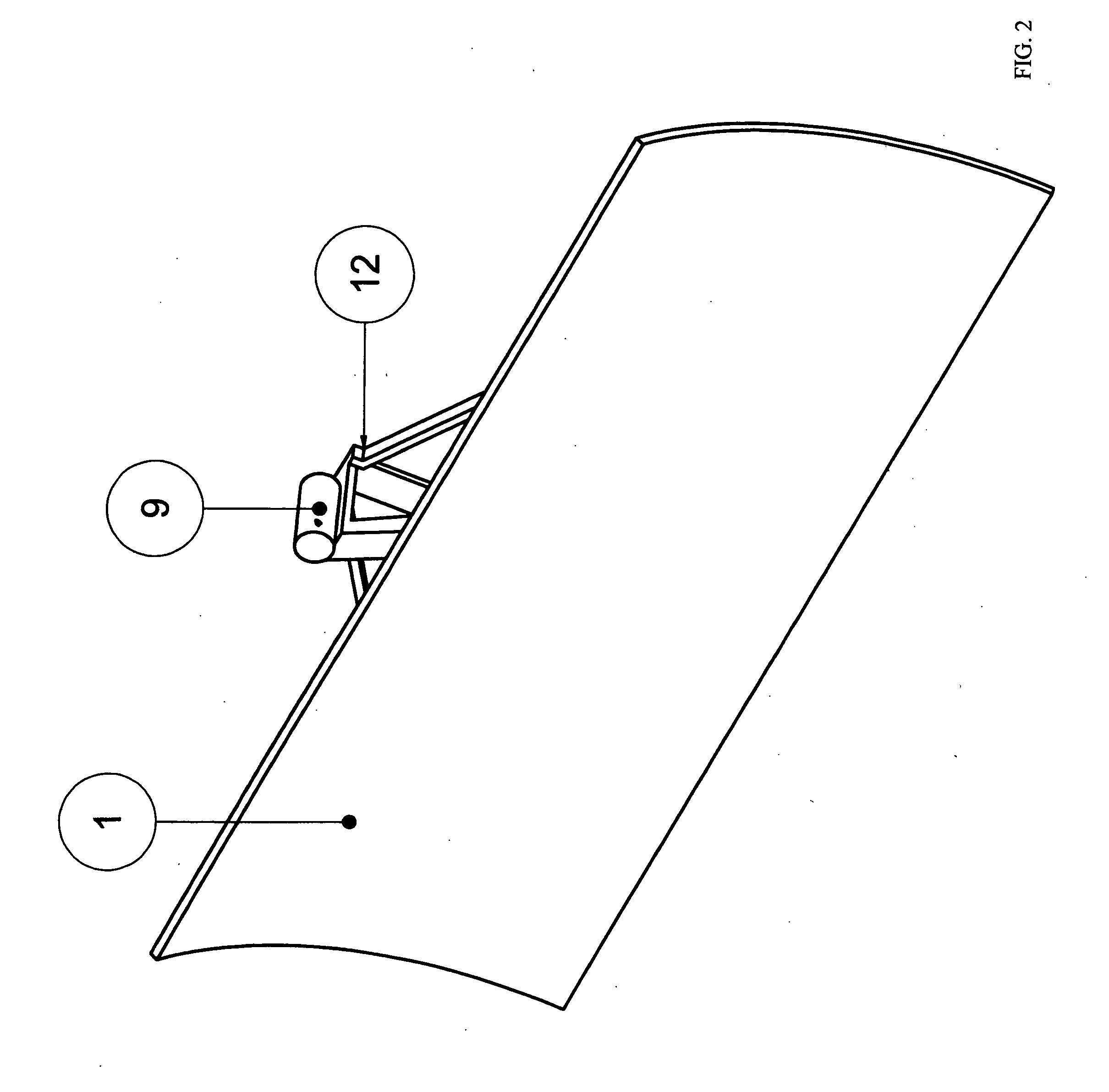
[0038]1. SHOVEL BLADE[0039]2. SLIDING PIVOTAL COLLAR[0040]3. SHOVEL HANDLE SHAFT[0041]4. BLADE ANGLE CONNECTOR MEANS-MALE SOCKET MEMBER[0042]5. SHOVEL HANDLE SHAFT-FEMALE SOCKET MEMBER[0043]6. HITCH PIN[0044]7. ARTICULATION MEANS-MALE SOCKET MEMBER[0045]8. ARTICULATION MEANS-FEMALE SOCKET MEMBER[0046]9. ARTICULATION MEANS[0047]10. FOOT SUPPORT[0048]11. BLADE ANGLE CONNECTOR MEANS[0049]12. STABILIZER SUPPORT[0050]13. SLIDING PIVOTAL COLLAR-THREADED GUIDE[0051]14. ARTICULATION MEANS-MALE SOCKET MEMBER CONNECTOR NUT[0052]15. BOLT-HITCH PIN ALTERNATE[0053]16. NUT-HITCH PIN ALTERNATE[0054]17. SHOVEL HANDLE SHAFT-RETAINING RING[0055]18. PRE-DRILLED OPENING

IN THE DRAWINGS

[0056]FIG. 1 is a three-dimensional rear view of the device showing the shovel blade, articulation means-male socket member, articulation means-female socket member, stabilizer support, articulation means, hitch pin, shovel handle shaft, blade angle connector means, sliding pivotal collar, shovel handle shaft r...


PUM


Abstract

A manually operable shovel for efficiently moving material, including a shovel blade, a shovel handle, a threaded joint for attaching the shovel blade to a pivotal collar which attaches the shovel handle shaft to a shovel blade joint, by means of a pressure fit socket interconnected to a support articulation device permanently affixed to the shovel blade, cooperating with the support member for positioning the blade to a pre-determined fixed angle relative to the direction of the blade movement, attaching the shovel handle shaft to the respective fixed angle settings by pressure fit sockets oriented generally at the respective handle/blade junction.
The pivotal collar cooperates with the shovel handle shaft to allow the shovel handle to angularly swivel as required to lock the pre-determined pressure fit sockets located at the lower span of the sides and center of the shovel blade relative to the axis of the upper support articulation device securing the handle.
The pressure fit connectors retain the handle in the pre-determined angles as engaged until overcome by rearward force against the shovel blade applied by the operator, disengaging at pressure fit sockets oriented at the respective handle/blade junctions, partially disengaging the shovel blade from handle shaft. The pivotal collar cooperates with the shovel handle shaft to allow the shovel handle to extend and distend as required to reengage at the pre-determined pressure fit sockets located at the lower span of the sides and center of the shovel blade relative to the axis of the upper support articulation device securing the handle.

Description

FIELD OF THE INVENTION[0001]This invention relates to a shovel particularly adapted for being manually used to shovel snow and other material, for example, mud, leaves, other yard debris and sawdust. The term “shovel” as used herein refers interchangeably to an implement which can be used to shovel i.e., lift, push and displace, the materials.[0002]Manually shoveling snow and other heavy material is physically demanding. Users generally alternate between a true “shoveling” motion where a quantity of the material is displaced from a surface onto the blade, the blade is lifted and the materials thrown off of the blade, and a “plowing” motion, where the shovel is pushed along the ground, pushing the material in advance of the blade. The “plowing” motion as referenced is potentially more efficient, since more material can be moved, without the need of lifting both the shovel and the material off of the ground. This motion can be much less demanding on the shoulders, back and arms. Howev...

Claims


Application Information

Patent Timeline
Patent Type & Authority Applications(United States)
IPC IPC(8): E01H5/02A01B1/02A01B1/22
CPCE01H5/02
Inventor TOWLES, HOWARD E.
Owner TOWLES HOWARD E
Why Eureka
Try Eureka