
Electronic Device Equipped with Programmable Key Layout and Method for Programming Key Layout

a technology of electronic devices and keys, applied in the direction of coding, keyboard-like devices, pulse techniques, etc., can solve the problems of easy waterproof problems, achieve the effect of convenient and comfortable operation of the keyboard, enhance the appearance design of the electronic device, and not be damaged

Inactive Publication Date: 2011-01-06
GETAC TECH CORP
View PDF4 Cites 10 Cited by
  • Summary
  • Abstract
  • Description
  • Claims
  • Application Information

AI Technical Summary

Benefits of technology

[0011]Through the electronic device and the method of the present invention, a user can define sensor points included in each sensor point grid and the correspondingly key codes in his / her preferred manner. Therefore, according to his / her preference and requirement, the user can adjust the proper size of a key (the amount of the sensor points included in a sensor point grid), gaps between the keys (gaps between the sensor point grid), and key lout (the key code corresponding to each sensor point grid). Moreover, multiple sensor point grids can be designed to the sensor points within a finger-width range, therefore the user can send key codes corresponding to multiple sensor point grids simultaneously by a single one touch.
[0013]Moreover, through the display panel, the users can look-and-feel the appearance of the keys and the three dimensions visual effect showing the keys being pressed. And displayed character can show the characters of one or more languages. Therefore, when the user operates the keyboard, the user can look at every character that he / she is going to enter, there is no on-screen small keyboard cutting the screen into multiple frames, so as to have the user to operate the keyboard conveniently and comfortably.

Problems solved by technology

In mechanical design, the waterproof issue is easy to be achieved and the material of the keys is not a consideration to the life-span of the keyboard.

Method used


Image

  • Electronic Device Equipped with Programmable Key Layout and Method for Programming Key Layout
  • Electronic Device Equipped with Programmable Key Layout and Method for Programming Key Layout
  • Electronic Device Equipped with Programmable Key Layout and Method for Programming Key Layout

Examples


first embodiment

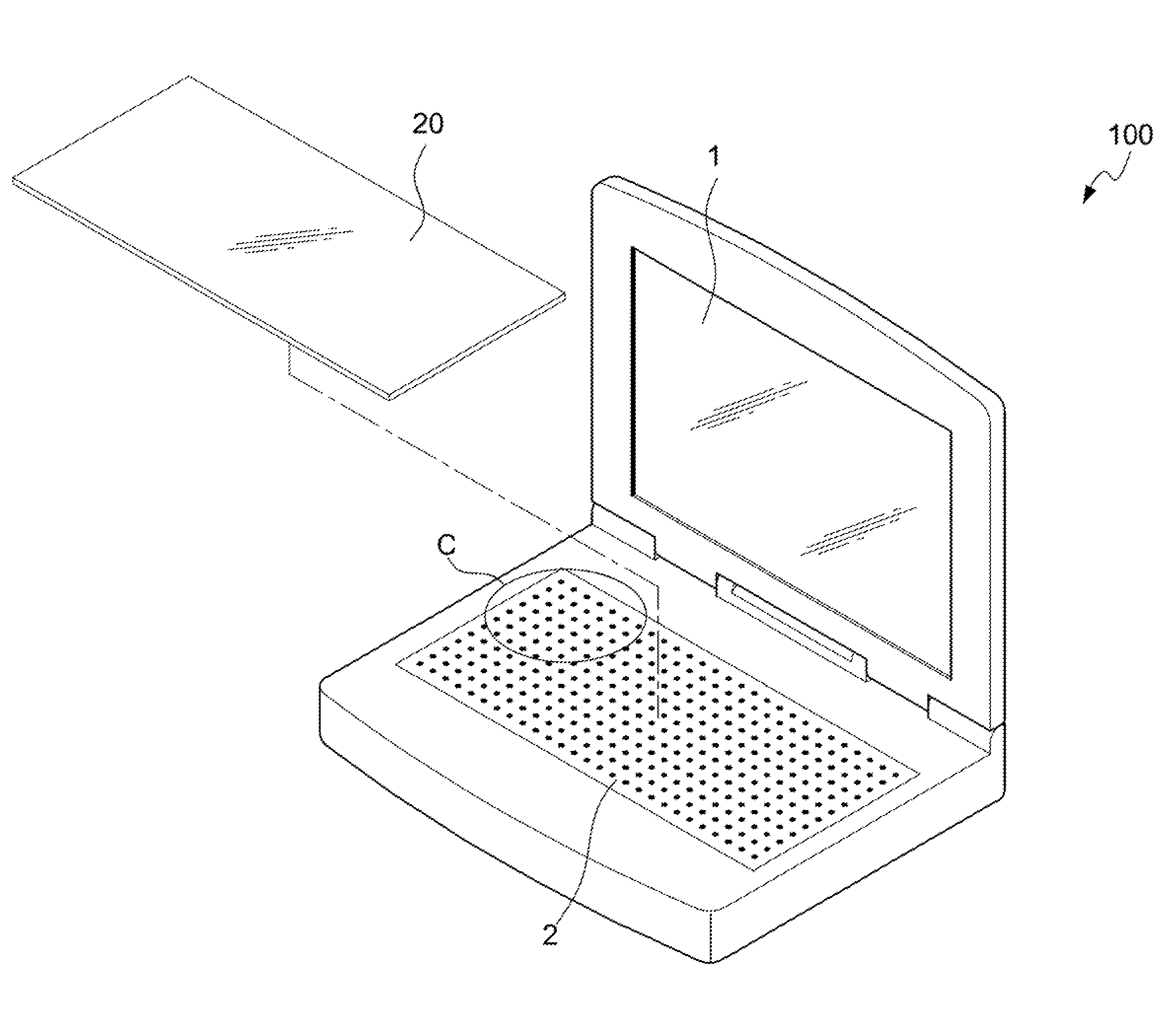
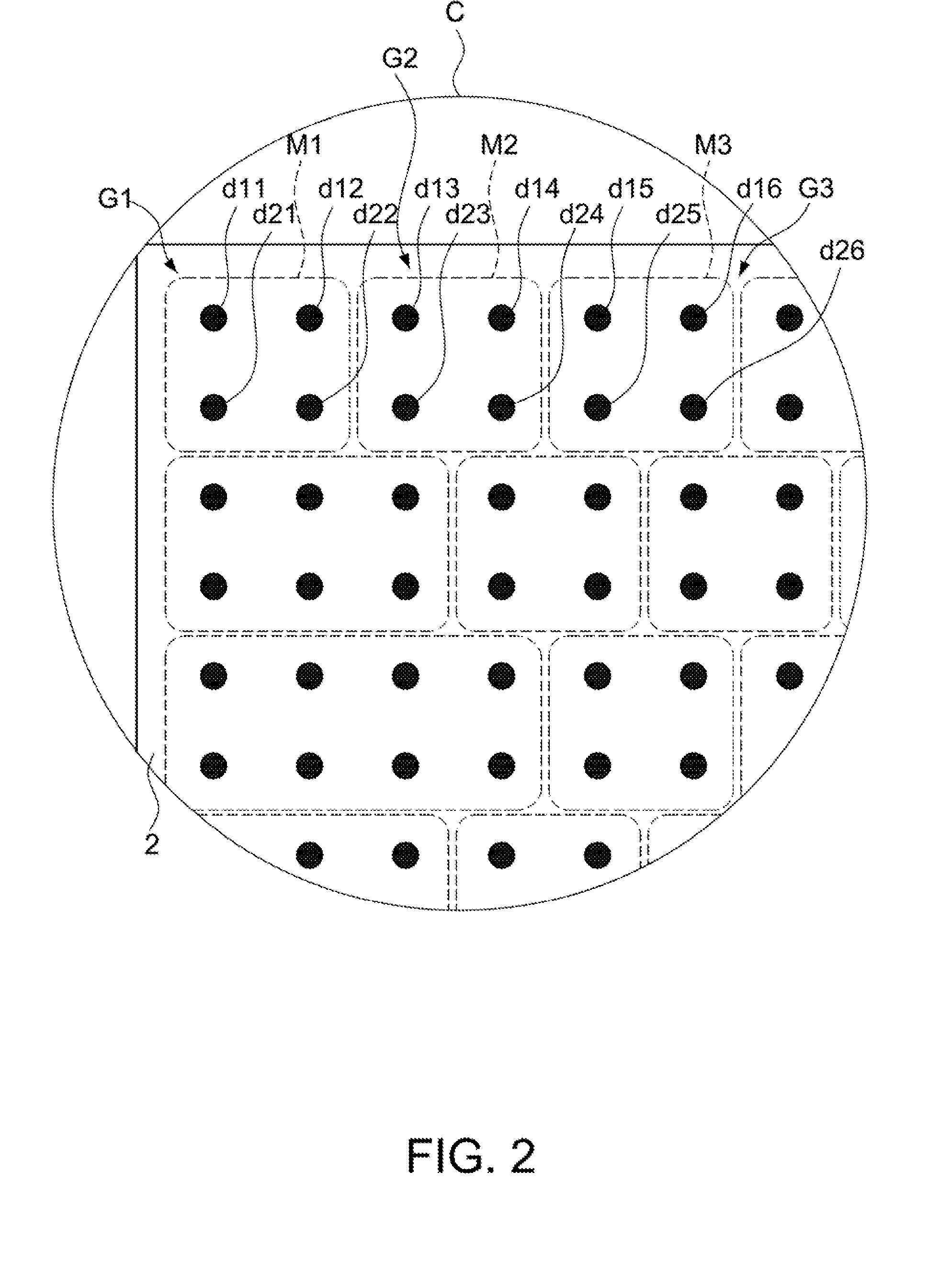
[0028]The corresponding functions of the sensor points d11, d12, d13, d14, d15, d16, d21, d22, d23, d24, d25, d26 are defined by the user. In the first embodiment, the sensor points d11, d12, d21, d22 circumscribed by the mark area M1 are defined as a sensor point grid G1 by the user; the sensor points d13, d14, d23, d24 circumscribed by the mark area are defined as a sensor point grid G2; the sensor points d15, d16, d25, d26 circumscribed by the mark area M3 are defined as a sensor point grid G3. The function of the sensor point grid G1, G2, or G3 is similar to a key of a keyboard in the prior art.

[0029]FIG. 3 and FIG. 4 are a block diagram and a keymap table according to the first embodiment of the present invention. The controlling circuit according to the first embodiment of the present invention includes a microprocessor 3, a memory module 4, and a temporary register 5. The microprocessor 3 is disposed in the electronic device 100. The microprocessor 3 is electrically coupled t...

second embodiment

[0042]FIG. 10 is flow chart according to the present invention. Firstly, the electronic device 100a provides a sensor point array assembly 2 including a plurality of sensor points d11, d12, d13, d14, d15, d16, d21, d22, d23, d24, d25, and d26 distributed over the sensor point array assembly (Step 201). Next, the electronic device 100a is started up (Step 202) to load the operating system of the electronic device 100a (Step 203). Then, the user can operate the electronic device 100a to launch the key layout editor program P (Step 204).

[0043]During the key layout editor program P is running, the user defines the sensor point grids G1, G2, G3 including at least one of the, sensor points d11, d12, d13, d14, d15, d16, d21, d22, d23, d24, d25, d26 in the sensor point array assembly 2 (Step 205).

[0044]Then, the user maps the defined sensor point grids G1, G2, G3 to designated key codes K1, K2, K3 and maps the defined sensor point grids G1, G2, G3 to corresponding displayed characters, so a...


PUM


Abstract

An electronic device equipped with programmable key layout in provided, which includes a microprocessor, a sensor point array assembly, and a memory module. The sensor point array assembly is electrically coupled to the microprocessor through an interface circuit. A plurality of sensor points is distributed over the sensor point array assembly. The memory module stores a keymap table, and at least a sensor point grid defined by a user and a key code corresponding to the sensor point grid are written into the keymap table. The sensor point grid includes at least one of the sensor points of the sensor point array assembly. When one or more of the sensor points of the sensor point array assembly is triggered, the microprocessor differentiates the key code corresponding to the sensor point grid including the triggered sensor point according to the keymap table in the memory module.

Description

BACKGROUND OF THE INVENTION[0001]1. Field of the Invention[0002]The present invention relates to keyboard of an electronic device, and more particularly, to an electronic device equipped with a programmable key layout and a method for programming the key layout of the electronic device.[0003]2. Related Art[0004]In a mechanical keyboard, every key includes a plastic key cap. The top of the key cap are marked with a character, a symbol, or a code. An elastic member and a sensor are disposed under the key cap. When the user presses the key cap, the sensor is triggered by the key cap and then sends a trigged signal to the electric device through a data transmission cable, so as to enter data or launch a data procession.[0005]Furthermore, the configuration and the size of a key, the gap between two adjacent keys, and the arrangement of all the keys are determined and unchangeable when the keyboard had been manufactured. Take the common electronic devices, a desktop computer and a laptop ...

Claims


Application Information

Patent Timeline
Patent Type & Authority Applications(United States)
IPC IPC(8): H03M11/00
CPCG06F3/0414G06F3/0238G06F3/04144
Inventor TUNG, LI-SHEN
Owner GETAC TECH CORP
Learn More