Image coding apparatus, control method therefor and computer program

a technology of image coding and control method, applied in the direction of signal generator with optical-mechanical scanning, color television with bandwidth reduction, signal generator, etc., can solve the problems of loss of picture quality, low coding efficiency, and less likely selection of intra-prediction modes

Active Publication Date: 2011-01-06
CANON KK
View PDF5 Cites 30 Cited by
  • Summary
  • Abstract
  • Description
  • Claims
  • Application Information

AI Technical Summary

Benefits of technology

[0012]The present invention provides good pictures both in the case where macroblocks belong to a flat aggregate area and in the opposite case.

Problems solved by technology

Therefore, in an aggregate area, such as a surface of a field, made up of a collection of mostly flat macroblocks, degradation is particularly conspicuous in macroblocks encoded in intra-prediction mode, resulting in loss of picture quality.
However, since the proposed technique described above only considers flatness on a macroblock by macroblock basis, the intra-prediction mode is less likely to be selected.
Consequently, compared to a method which simply selects inter-prediction mode or intra-prediction mode whichever has a smaller cost value, the proposed technique has a problem in that it provides a low coding efficiency, resulting in loss of picture quality.

Method used


Image

  • Image coding apparatus, control method therefor and computer program
  • Image coding apparatus, control method therefor and computer program
  • Image coding apparatus, control method therefor and computer program

Examples


first embodiment

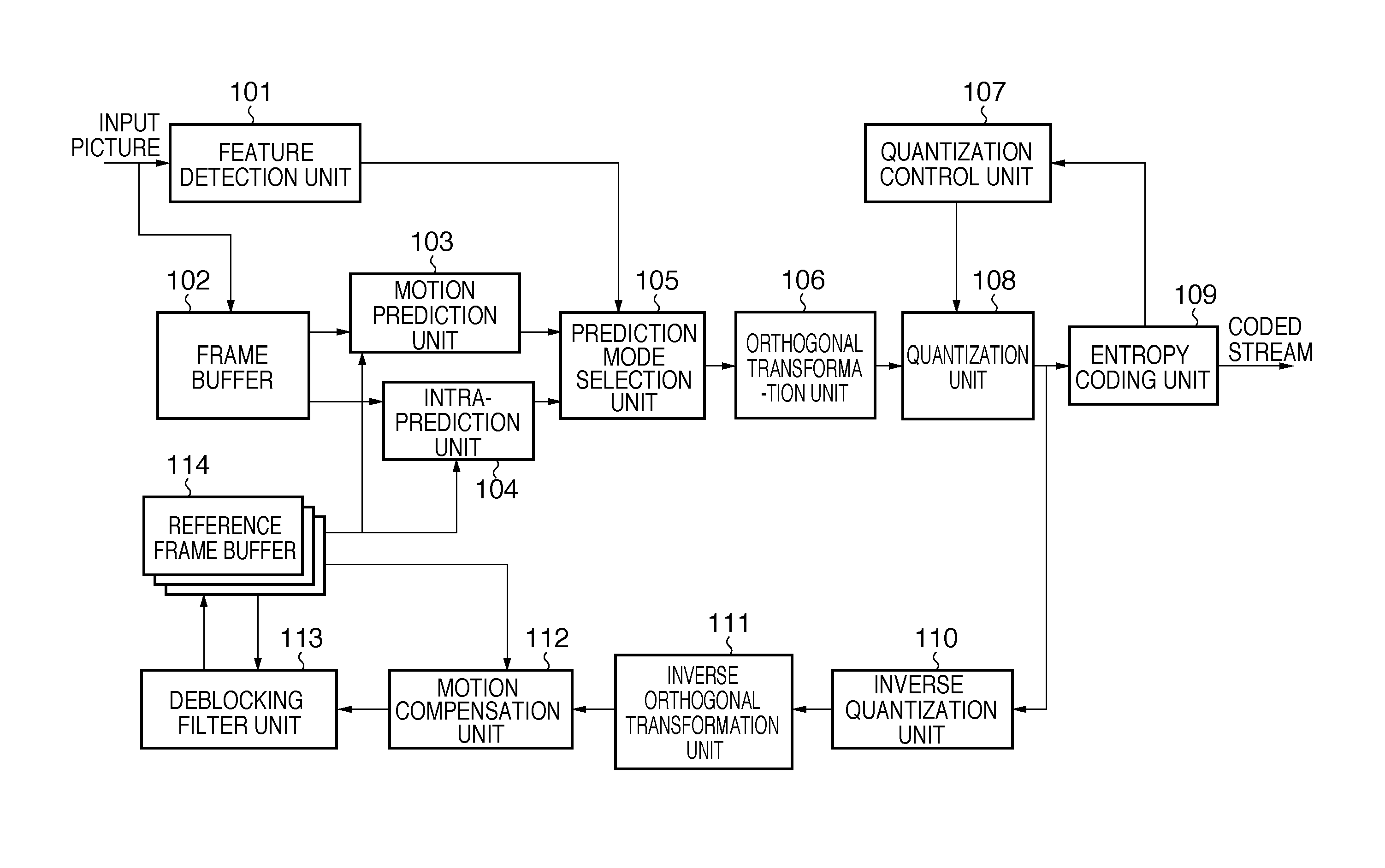
[0026]FIG. 1 is a block diagram illustrating a configuration of an image coding apparatus according to the present embodiment. A feature detection unit 101 accepts input of a picture to be subjected to an encoding process and determines which part is a flat aggregate area in the inputted picture. Determination results produced here are outputted to a prediction mode selection unit 105 as flat aggregate area flags which indicate whether each macroblock belongs to a flat aggregate area.

[0027]FIG. 5A shows an exemplary internal configuration of a feature detection unit 101. FIG. 5B shows a flowchart of procedures carried out by the feature detection unit 101 and prediction mode selection unit 105 to select a prediction mode. First, in S101, a flatness determination unit 501 receives an input picture and determines whether or not each macroblock (for example, 16 pixels×16 pixels) is flat. There are a few possible methods for flatness determination. For example, by calculating variance o...

second embodiment

[0042]FIG. 8 is a block diagram illustrating a configuration of an image coding apparatus according to a second embodiment of the present invention. Only differences from the first embodiment will be described in detail here. The second embodiment differs from the first embodiment in that a feature detection unit 801 operates differently from the feature detection unit 101 and that the quantization control unit 107 informs the feature detection unit 801 of quantization step size. First, if the quantization step size is larger than a determination threshold, the feature detection unit 801 determines whether the aggregate area is a flat aggregate area. This is because when the quantization step size is small, degradation is not great enough to be noticeable even if inter-prediction mode and intra-prediction mode coexist in a flat aggregate area.

[0043]FIG. 9 is a flowchart showing operation of the feature detection unit 801 according to the present embodiment. First, in S201, the featu...


PUM


Abstract

An image coding apparatus which divides an input picture into a plurality of macroblocks and performs a prediction encoding for each macroblock, comprising a unit for calculating flatness based on pixel values contained in a macroblock of interest and determining whether the macroblock of interest is a flat macroblock, a unit for storing determination results for each macroblock, a unit for determining, based on the determination results, whether the macroblock of interest determined to be a flat macroblock belongs to a flat area, a unit for selecting one of the inter-prediction mode and the intra-prediction mode as a prediction mode for an encoding process of the macroblock of interest based on determination results and on cost values of the inter-prediction mode and the intra-prediction mode, and a unit for performing predictive coding according to the selected prediction mode.

Description

BACKGROUND OF THE INVENTION[0001]1. Field of the Invention[0002]The present invention relates to an image coding apparatus, a control method therefor, and a computer program.[0003]2. Description of the Related Art[0004]In an encoding process of motion pictures, H. 264 encoding allows inter-prediction mode and intra-prediction mode to be selected in inter slices. In the inter-prediction mode, in relation to macroblocks to be encoded, block matching is performed between reference pictures and a current picture, and a position which gives the best coding efficiency is determined to be a motion vector position. To determine the motion vector position, generally a cost function is used, where the cost function is based on differential data obtained by subtraction between the reference picture and the current picture. Various cost functions are conceivable, and a typical example is given by Eq. (1).Cost=SATD+Qp×Mvcost   (1)where SATD is the sum of absolute Hadamard transform differences c...

Claims


Application Information

Patent Timeline
Patent Type & Authority Applications(United States)
IPC IPC(8): H04N7/32H04N19/50H04N19/107H04N19/136H04N19/176H04N19/196H04N19/423H04N19/503H04N19/51H04N19/593H04N19/60H04N19/61H04N19/91
CPCH04N19/176H04N19/147H04N19/14H04N19/11H04N19/109H04N19/61
Inventor KOBAYASHI, YUKIFUMI
Owner CANON KK
Why Eureka
Try Eureka