Method for propagating pseudo acoustic quasi-p waves in anisotropic media

a pseudo-acoustic quasi-p wave and anisotropic media technology, applied in the direction of mechanical measuring arrangements, instruments, using mechanical means, etc., can solve the problems of unstable wave propagation, computationally intensive three-dimensional (“3d”) anisotropic seismic modeling and migration, etc., to prevent the accumulation of energy and stable wavefield

Active Publication Date: 2011-01-13
CHEVROU USA INC
View PDF6 Cites 28 Cited by
  • Summary
  • Abstract
  • Description
  • Claims
  • Application Information

AI Technical Summary

Benefits of technology

[0006]The present invention provides both a pseudo-acoustic modeling method and a pseudo-acoustic migration method for anisotropic media. Aspects of embodiments of the present invention include a computer-implemented method for pseudo acoustic quasi-P wave propagation which remain stable in variable-tilt anisotropic media and is not limited to weak anisotropic conditions. The method also includes acquiring a seismic exploration volume for a subsurface region of interest, and determining a modeling geometry for the seismic exploration volume. The method further includes propagating at least one wavefield through the seismic exploration volume utilizing the modeling geometry for initial conditions and preventing the accumulation of energy along the axis of symmetry as well as ensuring positive stiffness coefficients in the stress-strain relations through the use of a small finite quasi-S wave velocity thereby producing a stable wavefield. The method includes utilizing the stable wavefield to generate subsurface images of the subsurface region of interest.

Problems solved by technology

Three-dimensional (“3D”) anisotropic seismic modeling and migration, however, are computationally intensive tasks.
However, these prior art pseudo-acoustic modeling and migration methods can become numerically unstable due to rapid lateral variations in tilt and / or certain rock properties (when the vertical velocity is greater than the horizontal velocity) and result in unstable wave propagation.

Method used


Image

  • Method for propagating pseudo acoustic quasi-p waves in anisotropic media
  • Method for propagating pseudo acoustic quasi-p waves in anisotropic media
  • Method for propagating pseudo acoustic quasi-p waves in anisotropic media

Examples


Embodiment Construction

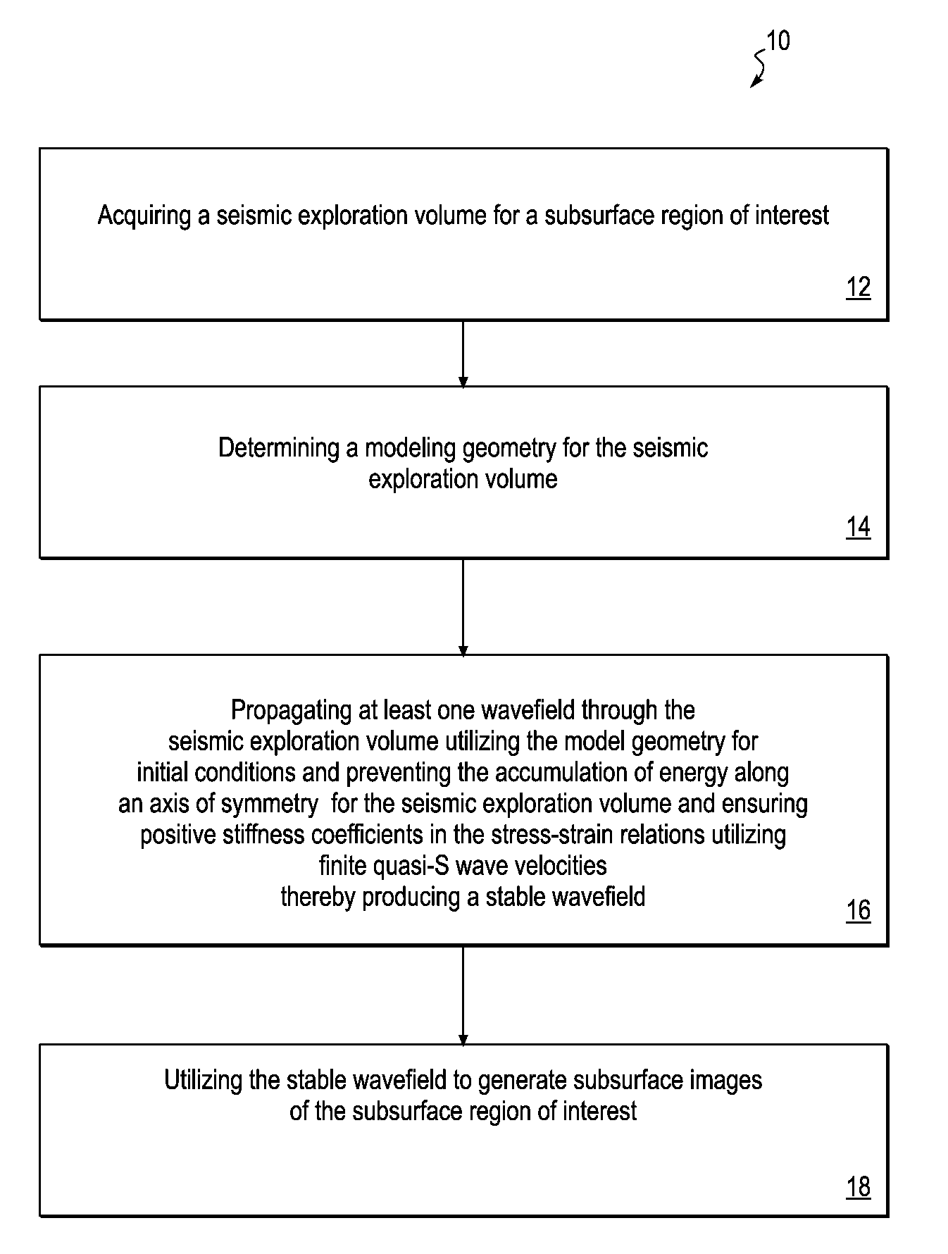
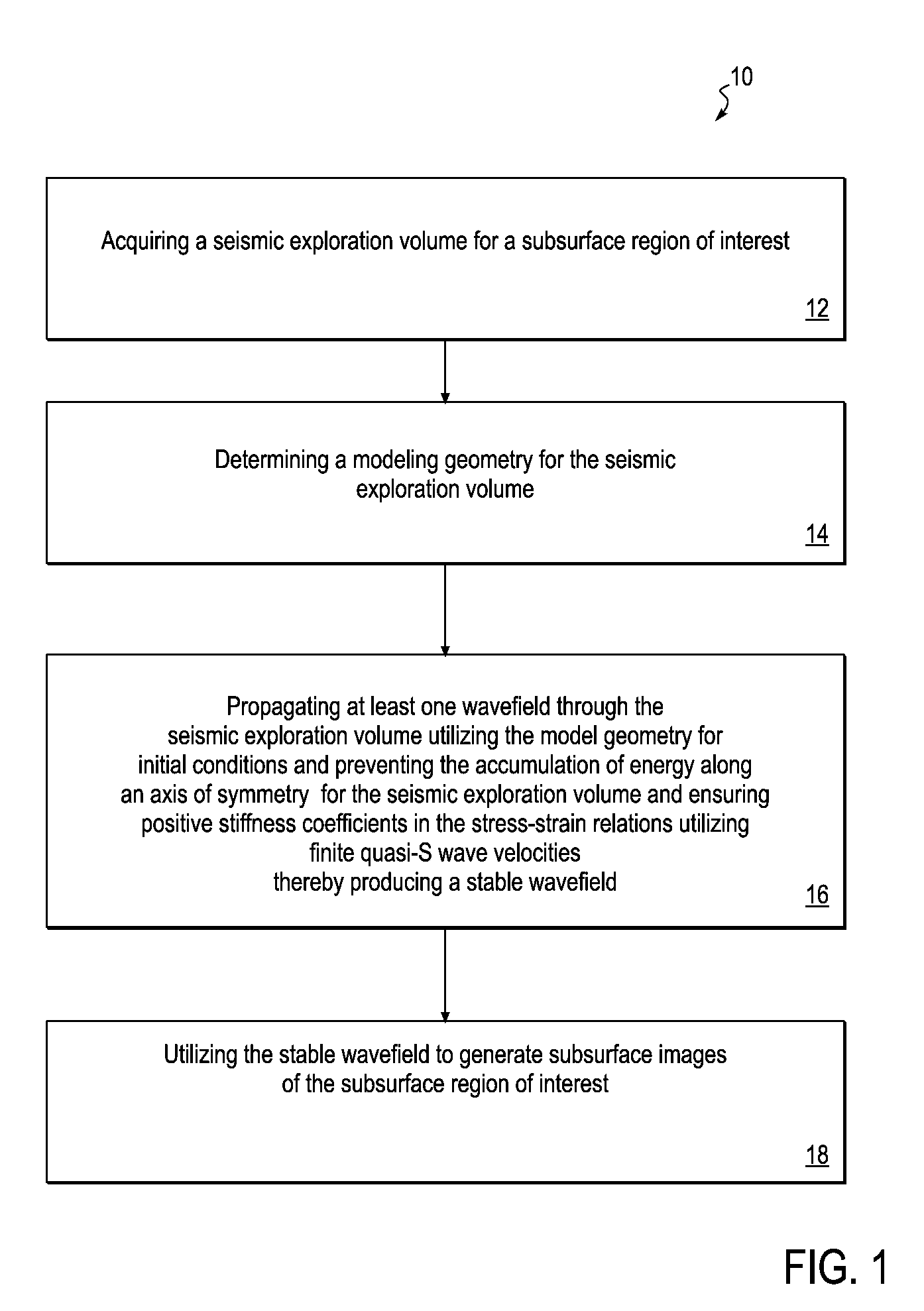
[0042]One embodiment of the present invention is illustrated in FIG. 1, wherein a flow chart 10 describes a method for propagating quasi-P waves which remain stable in anisotropic media with variable tilt. The present invention is not limited to weak anisotropic conditions. This particular embodiment includes acquiring a seismic exploration volume of a subsurface region of interest 12, and determining a modeling geometry for the seismic exploration volume 14. The embodiment further includes propagating at least one wavefield through the seismic exploration volume utilizing the modeling geometry for initial conditions and preventing the accumulation of energy along the axis of symmetry for the seismic exploration volume and ensuring positive stiffness coefficients in the stress-and-strain relations utilizing finite quasi-S wave velocities thereby producing a stable wavefield 16. The stable wavefield can then be utilized to generate subsurface images of the subsurface region of intere...


PUM


Abstract

A computer-implemented method for pseudo acoustic quasi-P wave propagation which remain stable in anisotropic media with variable tilt and is not limited to weak anisotropic conditions. The method includes acquiring a seismic exploration volume for a subsurface region of interest, and determining a modeling geometry for the seismic exploration volume. The method further includes propagating at least one wavefield through the seismic exploration volume utilizing the modeling geometry and initial conditions and preventing the accumulation of energy along the axis of symmetry of the seismic exploration volume and ensuring positive stiffness coefficients in the stress-strain relations through the use of finite quasi-S wave velocities thereby producing a stable wavefield. The method includes utilizing the stable wavefield to generate subsurface images of the subsurface region of interest.

Description

FIELD OF THE INVENTION[0001]The present invention relates generally to geophysical prospecting using seismic signals, and in particular a method for propagating pseudo-acoustic quasi-P wave propagation in variable tilted anisotropic media and using the propagated wavefields for subsurface property characterization.BACKGROUND OF THE INVENTION[0002]Anisotropy is ubiquitously observed in many oil and gas exploration areas (e.g., the Gulf of Mexico, the North Sea, and offshore West Africa) because of preferred ordering of minerals and defects related to stresses. In these regions, often the rock properties can be characterized as transversely isotropic (“TI”) media with either a vertical or tilted axis of symmetry. Wave propagation in anisotropic media exhibits different kinematics and dynamics from that in isotropic media, thus, it requires anisotropic modeling and migration methods to image reservoirs properly for oil and gas exploration.[0003]Three-dimensional (“3D”) anisotropic seis...

Claims


Application Information

Patent Timeline
Patent Type & Authority Applications(United States)
IPC IPC(8): G01V1/28
CPCG01V1/28G01V2210/67G01V2210/51
Inventor LIU, WEIBUBE, KENNETH P.
Owner CHEVROU USA INC
Why Eureka
Try Eureka