Apparatus for channel estimation, apparatus for equalization and method for equalization

a channel estimation and channel estimation technology, applied in the field of channel estimation, can solve problems such as inter-symbol interference, multi-path interference, degradation of equalization performance, etc., and achieve the effect of improving channel estimation accuracy, optimum equalizing performance, and improving channel estimation accuracy

Active Publication Date: 2011-01-13
NEC CORP
View PDF5 Cites 19 Cited by
  • Summary
  • Abstract
  • Description
  • Claims
  • Application Information

AI Technical Summary

Benefits of technology

[0133]The operation of the present invention is now explained. With the channel estimation apparatus and with the equalizing apparatus, according to the present invention, a single carrier signal is transformed into a frequency domain signal, and channel estimation and equalization are carried out by signal processing in the frequency domain. Before once transferring frequency domain channel estimation values to the time domain, channel estimation values of end-side subcarriers are copied to improve channel estimation accuracy. This channel estimation is used for calculating the weights for the equalization filter to achieve an optimum equalizing performance.
[0134]According to the present invention, described above, channel estimation is improved in accuracy. This channel estimation is used for calculating the weight of the equalization filter to achieve an optimum equalizing performance.

Problems solved by technology

In high speed data transmission with the use of the single carrier signal, an inter-symbol interference, which is ascribable to a multipath, that is, a multipath interference, has become of a problem.
In this case, a channel estimation value obtained may not be accurate, thus leading to degradation in the equalization performance.

Method used


Image

  • Apparatus for channel estimation, apparatus for equalization and method for equalization
  • Apparatus for channel estimation, apparatus for equalization and method for equalization
  • Apparatus for channel estimation, apparatus for equalization and method for equalization

Examples


exemplary embodiment 1

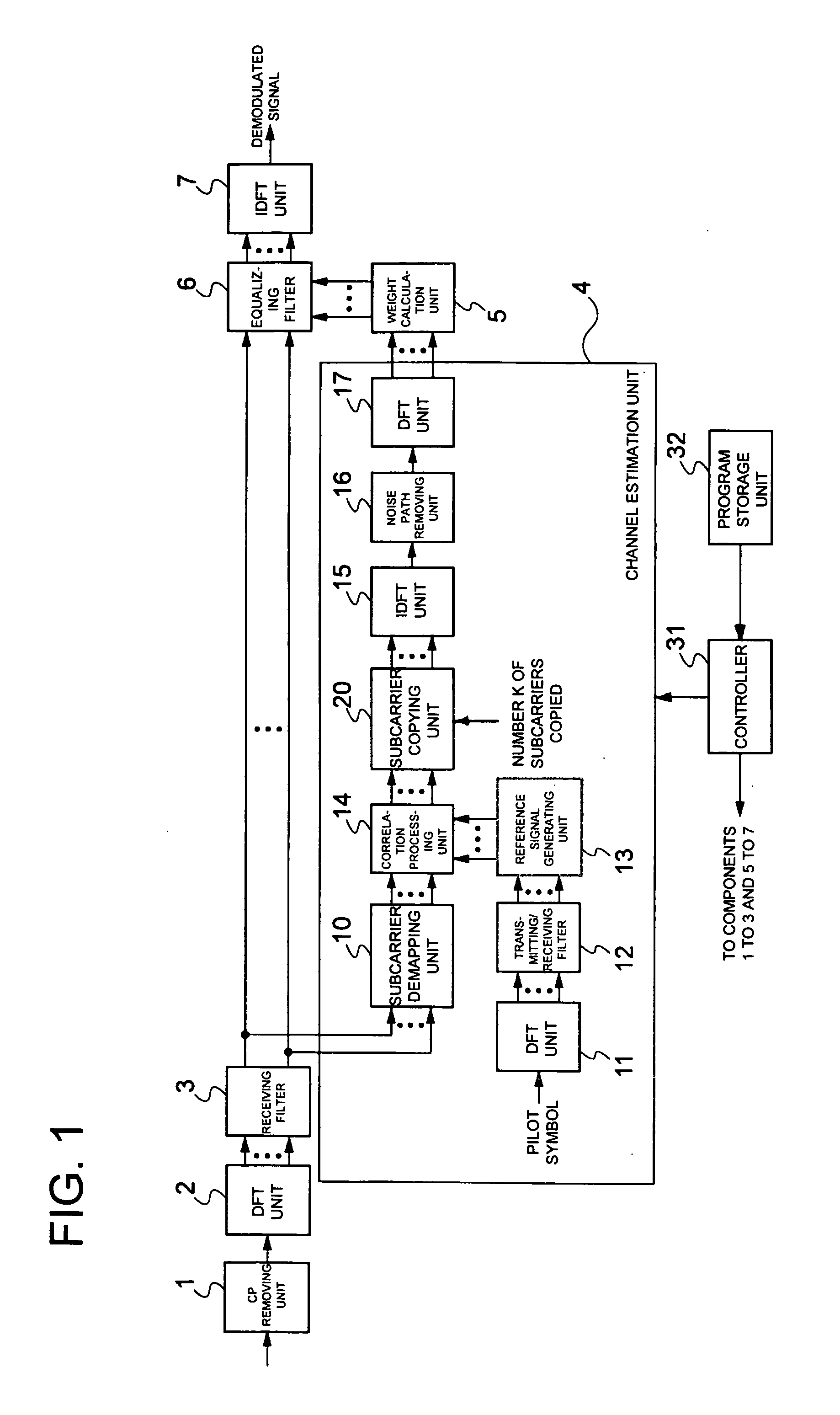
[0145]FIG. 1 is a block diagram showing a first exemplary embodiment of the channel estimation apparatus and the equalizing apparatus according to the present invention. The first exemplary embodiment of the channel estimation apparatus and the equalizing apparatus includes a CP removing unit 1, a DFT unit 2, a receiving filter 3, a channel estimation unit 4, a weight calculation unit 5, an equalization filter 6, an IDFT unit 7, a controller 31, and a program storage unit 32.

[0146]The channel estimation unit 4 includes a subcarrier demapping unit 10, DFT units 11, 17, a transmitting / receiving filter 12, a reference signal generating unit 13, a correlation processing unit 14, an IDFT unit 15, a noise path removing unit 16 and a subcarrier copying unit 20.

[0147]The controller 31 controls the CP removing unit 1, DFT unit 2, receiving filter 3, channel estimation unit 4, weight calculation unit 5, equalization filter 6 and the IDFT unit 7.

[0148]In the program storage unit 32, there is s...

example 2

[0170]FIG. 6 depicts a block diagram showing an Example 2 of the channel estimation apparatus and the equalizing apparatus according to the present invention. It is observed that, in FIG. 6, parts or components equivalent to those shown in FIG. 1 are denoted by the same reference numerals. The Example 2 of the channel estimation apparatus and the equalizing apparatus according to the present invention includes a CP removing unit 1, a DFT unit 2, a receiving filter 3, a channel estimation unit 25, a weight calculation unit 5, an equalization filter 6, an IDFT unit 7, a controller 31, and a program storage unit 32.

[0171]The channel estimation unit 25 includes a subcarrier demapping unit 10, DFT units 11, 17, a transmitting / receiving filter 12, a reference signal generating unit 13, a correlation processing unit 14, IDFT units 15, 26, a noise path removing unit 16, a transmission path calculation unit 27 and a subcarrier copying unit 28.

[0172]In Example 2, the operation of respective c...

example 3

[0180]Example 3 is relevant to a program for use in the channel estimation method and in the equalizing method. The channel estimation apparatus and the equalizing apparatus according to the present invention include the controller 31 and the program storage unit 32, as set forth above (see FIGS. 1 and 6).

[0181]In the program storage unit 32, there is stored a program for allowing the computer (controller 31) to execute the method for channel estimation and for equalization according to the present invention.

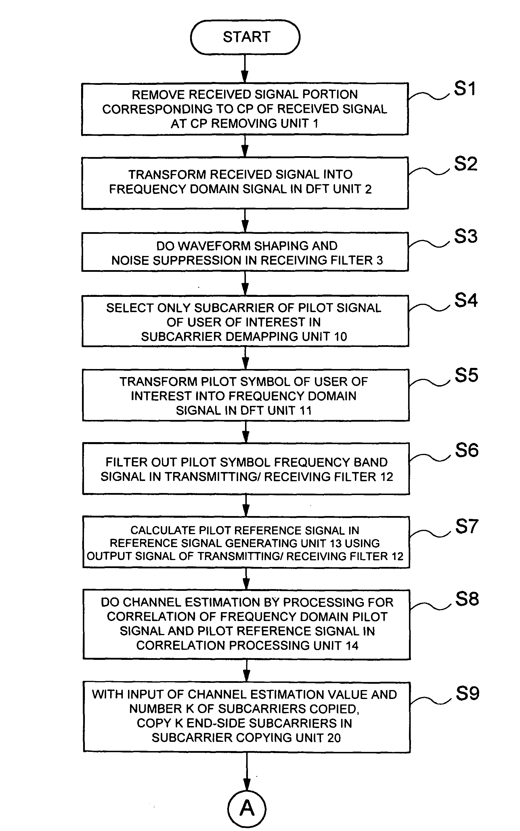
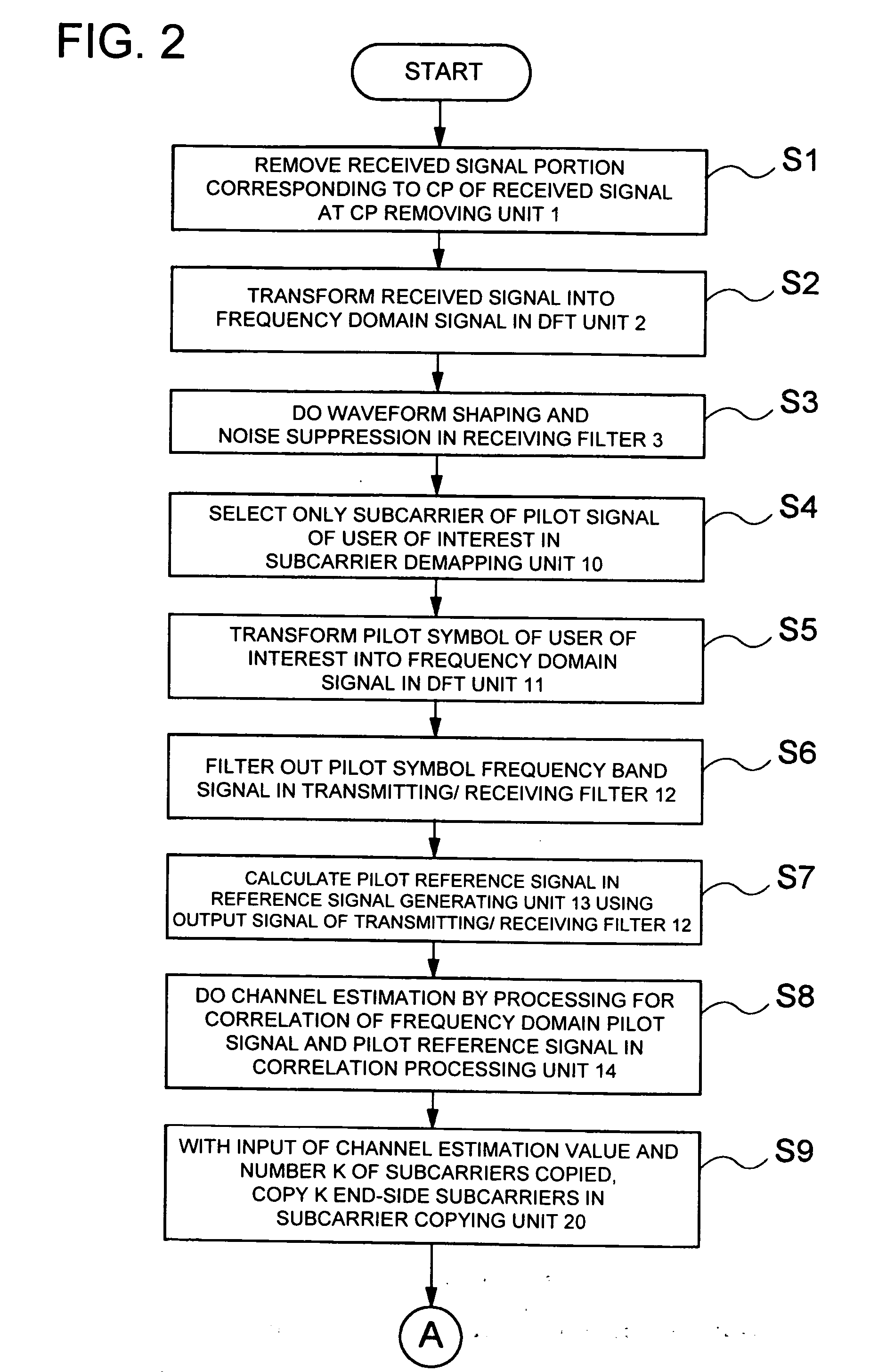
[0182]That is, the controller 31 reads out the program for the method of channel estimation and equalization, indicated in FIGS. 2, 3 and 7, from the program storage unit 32, and controls the respective components based on that program. The control contents have already been described above and hence the description is dispensed with.

[0183]With Example 3 of the present invention, described above, in which the channel estimation values of the end-side subcarriers are copied befor...


PUM


Abstract

The present invention provides a channel estimation apparatus in which channel estimation may be made higher than heretofore in accuracy and may be used for calculating the weight for an equalization filter to achieve an optimum equalizing performance. A subcarrier copying unit 20 copies K items of end-side subcarriers, using the channel estimation obtained by a correlation processing unit 14 and K which is a subcarrier copy number. An IDFT unit 15 transforms the channel estimation obtained at the subcarrier copying unit 20 into the time domain channel response. A noise path removing unit 16 removes noise paths from the channel response output from the IDFT unit 15. A DFT unit 17 performs DFT of the channel response, from which the noise paths are removed by the noise path removing unit 16, to output a noise-suppressed frequency domain channel estimation value. A weight calculation unit 5 inputs the frequency domain channel estimation value output from the DFT unit 17 to calculate an equalizing weight.

Description

TECHNICAL FIELD[0001]1. Related Application[0002]The present application claims priority rights based on Japanese Patent Application No. 2007-027435, filed in Japan on Feb. 7, 2007. The total disclosure of this Patent Application of the senior filing date is to be incorporated herein by reference.[0003]This invention relates to an apparatus for channel estimation, an apparatus for equalization, a method for channel estimation and a method for equalization. More particularly, it relates to an apparatus for channel estimation, an apparatus for equalization, a method for channel estimation and a method for equalization, according to which a single carrier signal is transformed into a frequency domain signal to carry out channel estimation and the processing for equalization by signal processing in the frequency domain.BACKGROUND ART[0004]In an uplink radio system of a next generation mobile communication, high efficiency of transmission power needs to be realized at a terminal side in ...

Claims


Application Information

Patent Timeline
Patent Type & Authority Applications(United States)
IPC IPC(8): H04L27/00H04L27/01
CPCH04L25/0204H04L25/0224H04L27/2647H04L25/03828H04L25/03834H04L25/03006H04B7/005
Inventor KIMATA, MASAYUKI
Owner NEC CORP
Why Eureka
Try Eureka