Radio apparatus

a radio apparatus and channel technology, applied in the field of radio apparatuses, can solve the problems of large error in channel estimation based on said channel estimation known signal, subject to the effect of frequency selective fading, distortion, etc., and achieve the effect of preventing the degradation of transmission efficiency and improving channel estimation accuracy

Active Publication Date: 2012-04-03
HERA WIRELESS
View PDF10 Cites 9 Cited by
  • Summary
  • Abstract
  • Description
  • Claims
  • Application Information

AI Technical Summary

Benefits of technology

[0015]The present invention has been made under such circumstances and a general purpose thereof is to provide a radio apparatus that enhances the accuracy of channel estimation by preventing the degradation in transmission efficiency at the time of transmitting known signals for use in channel estimation.
[0019]According to this embodiment, the data for a terminal apparatus to which a known signal, whose number of streams is greater than that of the data signals, is to be transmitted is specified and the known signal is added to the specified data, so that there is no longer need for transmitting a separate known signal. Hence, the deterioration of transmission efficiency can be prevented.
[0021]The generation unit may generate a plurality of packet signals from the plurality of data signals and may have a data signal, to which a known signal is appended, contained in a posterior part of packet signal in the plurality of packet signals, and the transmitter may transmit the plurality of packet signals generated by the generation unit, at an interval shorter than an interval at which a packet signal is to be transmitted normally. In such a case, when a plurality of packet signals are transmitted at an interval shorter than an interval at which a packet signal is to be transmitted normally, data signals to which known signals are appended are transmitted, so that the transmission efficiency can be enhanced.
[0023]The generation unit is such that when known signals whose number of streams is greater than the number of data signals are appended, the known signals are appended to a main stream where a data signal is assigned and a sub-stream where no data signal is assigned, respectively, and a known signal in the sub-stream is assigned to a timing other than a timing to which a data signal and a known signal in the main stream are assigned. In such a case, the timing, to which a known signal is assigned, in a stream where a data signal is assigned is shifted or staggered from the timing, to which a known signal is assigned, in a stream where no data signal is assigned. Hence, the received powers of both the streams can be brought closer to each other and the deterioration of estimation in specifying a channel can be prevented.
[0030]different values of amounts of timing shift are set to the plurality of streams, respectively. In such a case, the timing shift amounts for the respective known signals assigned to a plurality of streams are of the same values, so that a receiving apparatus can cope easily when there are changes in streams that have data assigned.
[0031]In the generation unit, the known signal and the extensional known signal may be formed by repeating a predetermined unit in time domain, a combination of signs of the predetermined unit may be defined so that an orthogonality holds among the streams, and the combination of signs of the predetermined unit may be so defined as to be fixed in the plurality of streams, respectively. In this case, the combination of signs is fixed, the processing can be made simpler.

Problems solved by technology

The packet signals in such a wireless LAN are generally transferred via a time-varying channel environment and are also subject to the effect of frequency selective fading.
In so doing, when the strength of channel estimation known signal of a stream where the AGC known signal is not assigned is larger, there is a strong possibility that said channel estimation known signal may be amplified to such a degree that distortion is caused by AGC.
As a result thereof, the error in channel estimation based on said channel estimation known signal becomes large.
Hence, there is a possibility that the gain set by the AGC known signal is not suitable for the modulation of data.
As a result, the demodulated data are subject to errors.

Method used


Image

  • Radio apparatus
  • Radio apparatus
  • Radio apparatus

Examples


Embodiment Construction

[0057]The invention will now be described based on the following embodiments which do not intend to limit the scope of the present invention but exemplify the invention. All of the features and the combinations thereof described in the embodiments are not necessarily essential to the invention.

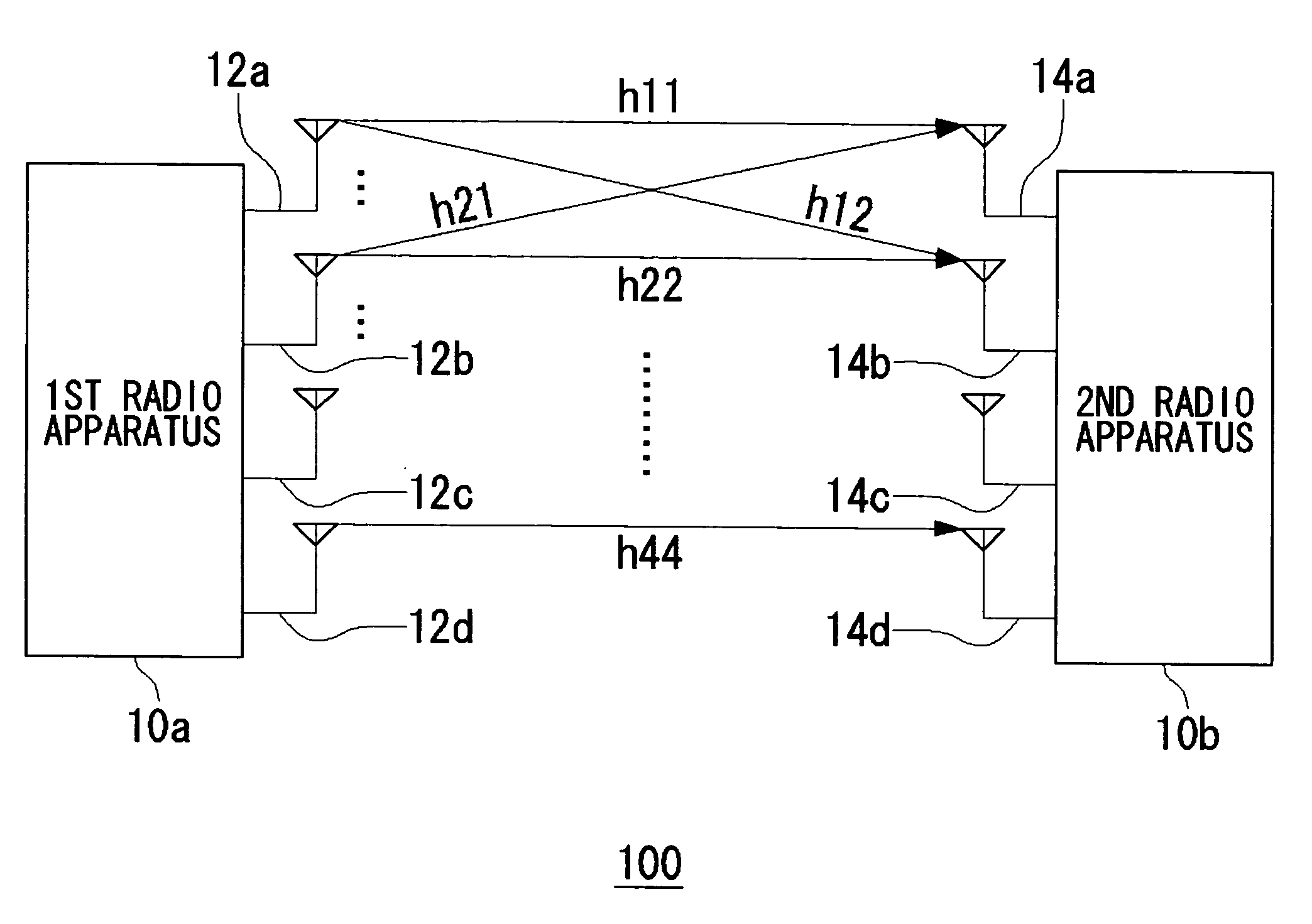
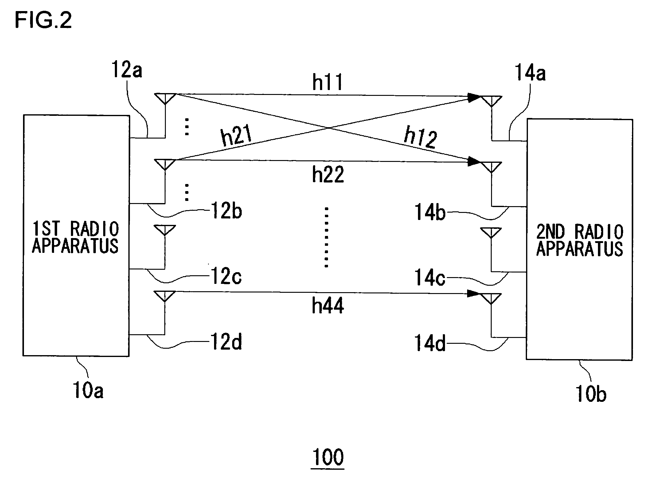
[0058]An outline of the present invention will be given before a specific description thereof. Embodiments of the present invention relate to a MIMO system comprised of at least two radio apparatuses. One of the radio apparatuses corresponds to a transmitting apparatus whereas the other thereof corresponds to a receiving apparatus. The transmitting apparatus generates one packet signal composed of a plurality of streams. In particular, a description will be given here of a processing performed when the transmitting apparatus transmits training signals. Any known technique may be used for the adaptive modulation processing using the aforementioned rate information and the beamforming and theref...


PUM


Abstract

Among destination terminal apparatuses to which a plurality of data signals are to be transmitted, a control unit specifies a terminal apparatus to which a known signal, whose number of streams is greater than the number of streams for a data signal, is to be transmitted. The control unit appends a known signal, whose number of streams is greater than the number of streams for this data signal, to the data signal which is to be transmitted to the specified terminal apparatus. While assigning the data signal, to which the known signal has been appended, to a posterior part of the plurality of data signals, the control unit generates packet signals in a manner that a known signal, whose number of streams corresponds to the number of streams for a data signal in a header portion, is appended to a header portion of the plurality of data signals.

Description

RELATED APPLICATIONS[0001]This application claims the benefit of U.S. Provisional Patent Application No. 60 / 718,302, filed on Sep. 20, 2005 the disclosure of which Application is incorporated by reference herein.BACKGROUND OF THE INVENTION[0002]1. Field of the Invention[0003]The present invention relates to radio apparatuses, and it particularly relates to a radio apparatus using multiple subcarriers.[0004]2. Description of the Related Art[0005]An OFDM (Orthogonal Frequency Division Multiplexing) modulation scheme is one of multicarrier communication schemes that can realize the high-speed data transmission and are robust in the multipath environment. This OFDM modulation scheme has been applied to the wireless standards such as IEEE802.11a / g and HIPERLAN / 2. The packet signals in such a wireless LAN are generally transferred via a time-varying channel environment and are also subject to the effect of frequency selective fading. Hence, a receiving apparatus generally carries out the ...

Claims


Application Information

Patent Timeline
Patent Type & Authority Patents(United States)
IPC IPC(8): H04L27/28H04J99/00
CPCH04L1/06H04L5/0023H04L5/0048H04L27/2608H04L27/261H04L27/2613H04L5/023H04L25/0204H04L25/0224H04L25/0226H04L2025/03414H04L2025/03426H04L27/26132H04L5/0044
Inventor NAKAO, SEIGO
Owner HERA WIRELESS
Why Eureka
Try Eureka