Image heating apparatus

Inactive Publication Date: 2011-01-13
CANON KK
View PDF4 Cites 8 Cited by
  • Summary
  • Abstract
  • Description
  • Claims
  • Application Information

AI Technical Summary

Benefits of technology

[0010]A principal object of the present invention is to provide an image heating apparatus capable of suppressing a lowering in amount of a lubricant on an inner surface of a belt member.

Problems solved by technology

As a result, the fixing device is accompanied with a problem of durability.

Method used


Image

  • Image heating apparatus
  • Image heating apparatus
  • Image heating apparatus

Examples


Embodiment Construction

[0024]Hereinbelow, with reference to the drawings, embodiments of the present invention will be described. However, dimensions, materials, shapes, and relative arrangements, and the like of constituent elements described in the following embodiments may be appropriately be changed depending on constitutions and various conditions for apparatuses or devices to which the present invention is applied. Therefore, it should be understood that the present invention is not limited to those specifically described in the following embodiments unless otherwise noted specifically.

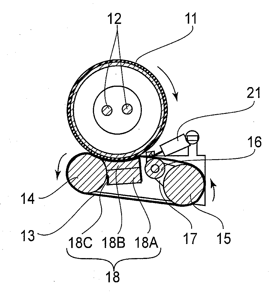
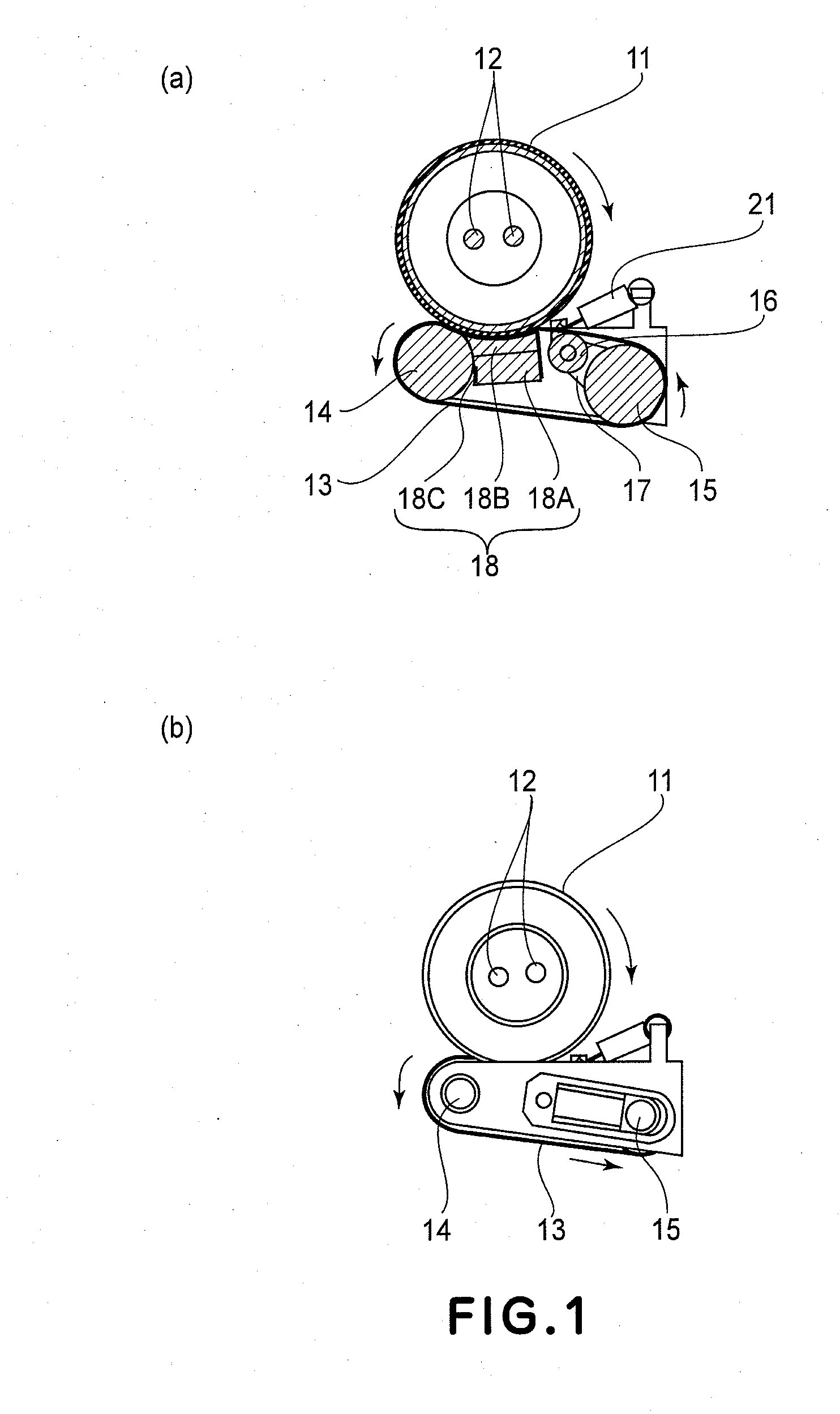
[0025]Further, in the following description, a belt conveying device rotating in press-contact with a roller is exemplified but the present invention is not limited thereto. For example, it is also possible to use the belt conveying device rotating in press-contact with a drum-like member covered with film and the belt conveying device of a twin belt type in which two belts rotate in press-contact with each other.

[002...


PUM


Abstract

An image heating apparatus includes a rotatable member; a belt member contactable to the rotatable member; a pressing member for pressing the belt member against the rotatable member to form a nip in which a recording material is nipped and conveyed; and a sheet member for covering a pressing surface of the pressing member at which the pressing member presses the belt member. The sheet member is mounted on the pressing member so as to have a first area in which an end portion thereof is located outside an end portion of the belt member with respect to a widthwise direction perpendicular to a conveying direction of the recording material and which includes a portion opposing the pressing surface, and so as to have a second area in which the end portion thereof is located inside the end portion of the belt member with respect to the widthwise direction.

Description

FIELD OF THE INVENTION AND RELATED ART[0001]The present invention relates to an image heating apparatus in which a lubricant is applied onto an inner surface of a belt member supported by a supporting member and an image on a recording material is heated.[0002]As the image heating apparatus, it is possible to use, e.g., a fixing apparatus (fixing device) for fixing a transferred unfixed image on a recording medium (member) or a glossiness-increasing apparatus for increasing glossiness of the image fixed on the recording material under application of heat and pressure.[0003]As a conventional constitution of the image heating apparatus for fixing the transferred unfixed image on the recording material, a constitution in which the unfixed image was fixed on the recording material at a press-contact portion (in a nip) created by causing a belt conveying device as shown in FIGS. 6(a) and 6(b) to press-contact a heating roller including a heat source has been known.[0004]In the belt conve...

Claims


Application Information

Patent Timeline
IPC IPC(8): G03G15/20
CPCG03G15/206G03G2215/2009
Inventor OKAMOTO, OSAMU
Owner CANON KK
Why Eureka
Try Eureka