Diffraction optical device and optical system including same

a technology of optical applied in the field of diffraction/optical devices and optical systems, can solve the problems of reducing diffraction efficiency, reducing diffraction efficiency, and unwanted flare light, and achieve the effect of suppressing the lowering of diffraction efficiency

Inactive Publication Date: 2006-03-21
CANON KK
View PDF28 Cites 3 Cited by
  • Summary
  • Abstract
  • Description
  • Claims
  • Application Information

AI Technical Summary

Benefits of technology

[0018]Accordingly, it is an object of the present invention to provide a diffraction optical device capable of suppressing a lowering of diffraction efficiency due to the dependency thereof upon the incident angle of light, and an optical system including the diffraction optical device.

Problems solved by technology

Corresponding to a lowering of the diffraction efficiency for light of the design 1-order, diffracted light of other orders (0- and 2-orders, etc.) occurs and gives rise to unwanted flare light.
This raises the problem that the diffraction efficiency is greatly reduced depending upon the layout of the diffraction optical device in the optical system.

Method used


Image

  • Diffraction optical device and optical system including same
  • Diffraction optical device and optical system including same
  • Diffraction optical device and optical system including same

Examples


first embodiment

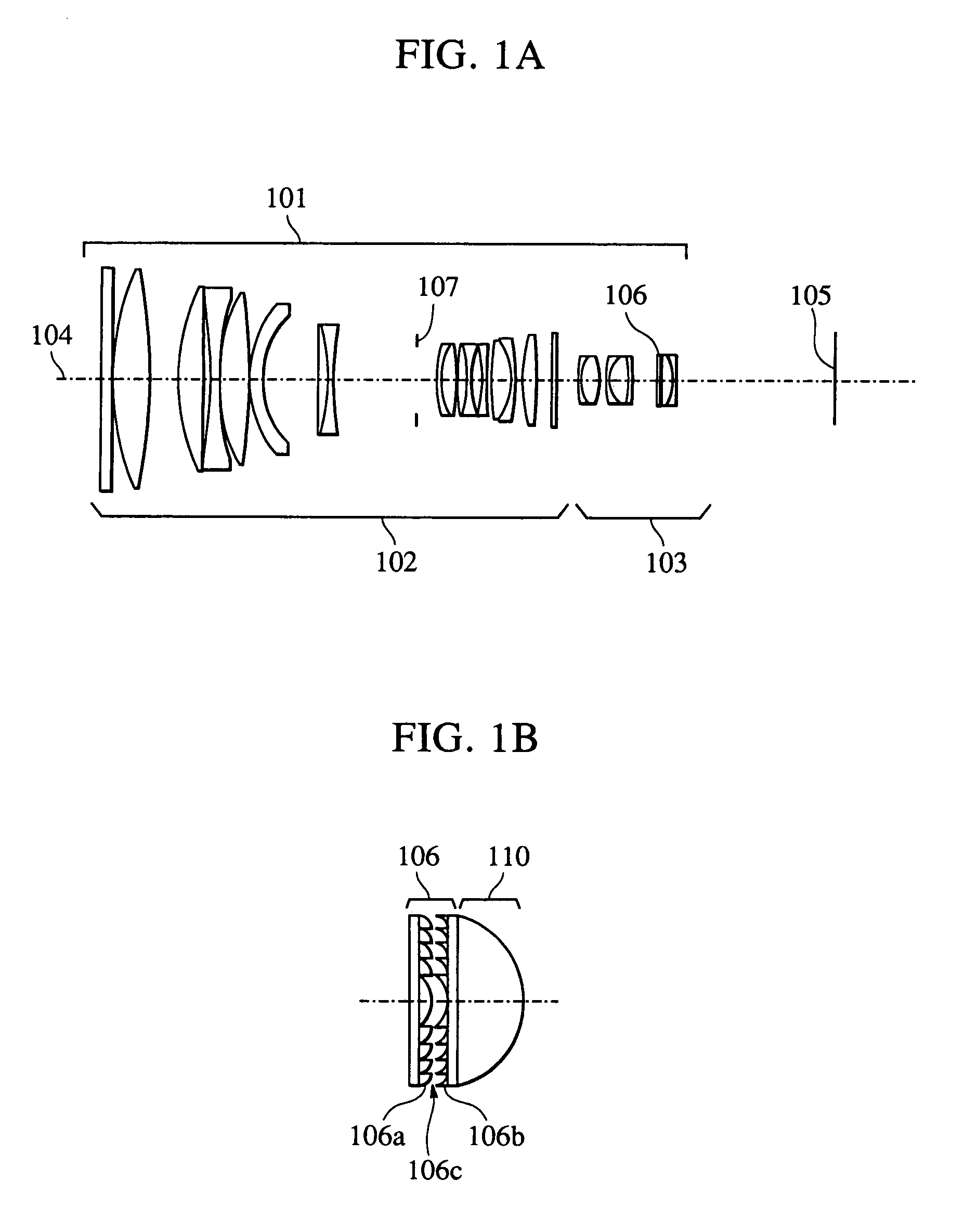
[0038]FIG. 1A is a sectional view of an optical system according to a first embodiment of the present invention.

[0039]This embodiment represents the case where a diffraction optical device is employed in an extender for a photographic lens.

[0040]In FIG. 1A, numeral 101 denotes an overall optical system comprising a master lens 102, an extender 103, and an iris 107. Numeral 105 denotes an image plane and 104 denotes an optical axis. A diffraction optical device 106 is provided within the extender 103.

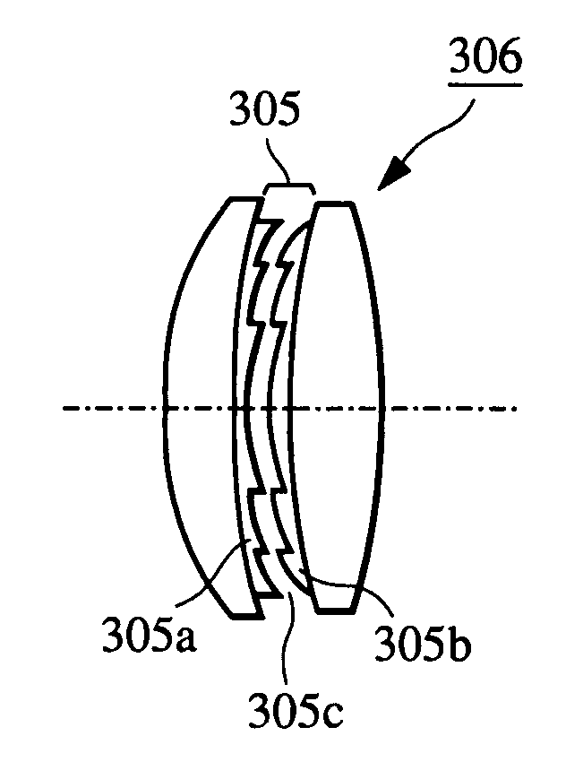
[0041]FIG. 1B schematically shows the structure of the diffraction optical device according to this embodiment. As shown in FIG. 1B, a first diffraction element 106a having a positive power (power ψ=1 / f: f is the focal length) and a second diffraction element 106b having a negative power are arranged adjacent to each other with an air layer 106c interposed between them. The first diffraction element 106a having a positive power is arranged on the side nearer to an object (i.e., on the li...

second embodiment

[0048]FIG. 4A is a sectional view of an optical system according to a second embodiment of the present invention. In FIG. 4A, numeral 201 denotes an optical system including a diffraction optical device 0.202, an optical axis 203, an image plane 204, and an iris 205. This embodiment represents the case where the diffraction optical device is applied to a telephoto lens for a photographic lens.

[0049]FIG. 4B schematically shows the structure of the diffraction optical device according to this embodiment. As shown in FIG. 4B, a first diffraction element 202a having a negative power and a second diffraction element 202b having a positive power are arranged in an adjacently superimposed relation between two base plates with an air layer 202c interposed between both the diffraction elements.

[0050]In this second embodiment, as shown, the first diffraction element 202a having a negative power is arranged on the side nearer to an object. In FIG. 4B, grating portions of the first and second d...


PUM


Abstract

A diffraction optical device includes a first diffraction element and a second diffraction element arranged adjacent to each other. One of the first diffraction element and the second diffraction element has a positive power, and the other has a negative power. The first diffraction element reduces the incident angle of light upon the second diffraction element. As a result, a lowering of diffraction efficiency due to the dependency thereof upon the incident angle of light is suppressed, and flare light is prevented from occurring due to diffracted light of unnecessary orders.

Description

BACKGROUND OF THE INVENTION[0001]1. Field of the Invention[0002]The present invention relates to a diffraction / optical device and an optical system including the diffraction optical device. More particularly, the present invention is intended to realize a diffraction optical device capable of suppressing the occurrence of flare light due to diffracted light of unnecessary orders, and an optical system including the diffraction optical device.[0003]2. Description of the Related Art[0004]Hitherto, there is known a method for reducing chromatic aberration by combining plural kinds of glass materials with each other. Another advanced method for reducing chromatic aberration by providing a diffraction optical device 3, which develops a diffraction action, on a lens surface or in part of an optical system is disclosed in the literature of SPIE Vol. 1354 International Lens Design Conference (1990), Japanese Patent Laid-Open No. 4-213421 and No. 6-324262, U.S. Pat. No. 5,044,706, etc. This ...

Claims


Application Information

Patent Timeline
Patent Type & Authority Patents(United States)
IPC IPC(8): G02B5/18G02B27/44G02B13/00G02B27/00
CPCG02B5/18G02B27/4277G02B27/4211G02B27/0018
Inventor KOBAYASHI, SHUICHI
Owner CANON KK
Why Eureka
Try Eureka