Methods and systems for end of travel harshness reduction

Active Publication Date: 2011-01-13
STEERING SOLUTIONS IP HLDG
View PDF3 Cites 10 Cited by
  • Summary
  • Abstract
  • Description
  • Claims
  • Application Information

AI Technical Summary

Benefits of technology

[0005]Accordingly, a control system for a steering system is provided. The control system includes a first module that selectively determines a

Problems solved by technology

A negative impression can occur if there is a harsh, abrupt feeling when steering into the corners.
In some applications, a metal-on-metal clunk due to the steering rack end of travel hardware causes both audible and tactile annoyances.

Method used


Image

  • Methods and systems for end of travel harshness reduction
  • Methods and systems for end of travel harshness reduction
  • Methods and systems for end of travel harshness reduction

Examples


Embodiment Construction

stem in accordance with the invention;

[0010]FIG. 3 is a dataflow diagram illustrating a steering control system in accordance with the invention;

[0011]FIG. 4 is a flowchart illustrating a steering control method in accordance with the invention;

[0012]FIG. 5 is a flowchart illustrating a gain determination method in accordance with the invention; and

[0013]FIG. 6 is a flowchart illustrating a damping determination method in accordance with the invention.

DETAILED DESCRIPTION

[0014]The following description is not intended to limit the present disclosure, application, or uses. It should be understood that throughout the drawings, corresponding reference numerals indicate like or corresponding parts and features.

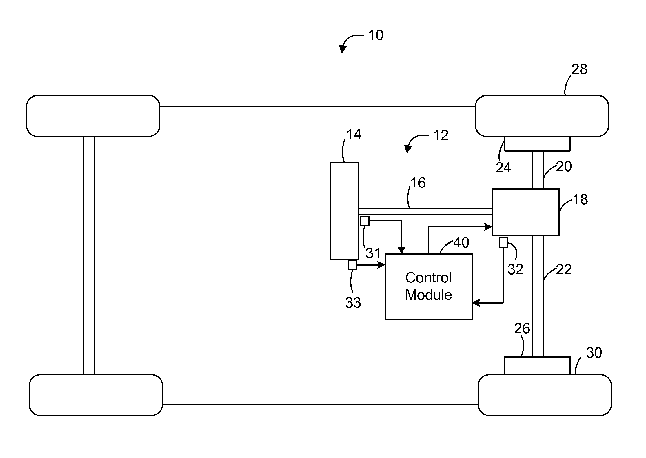
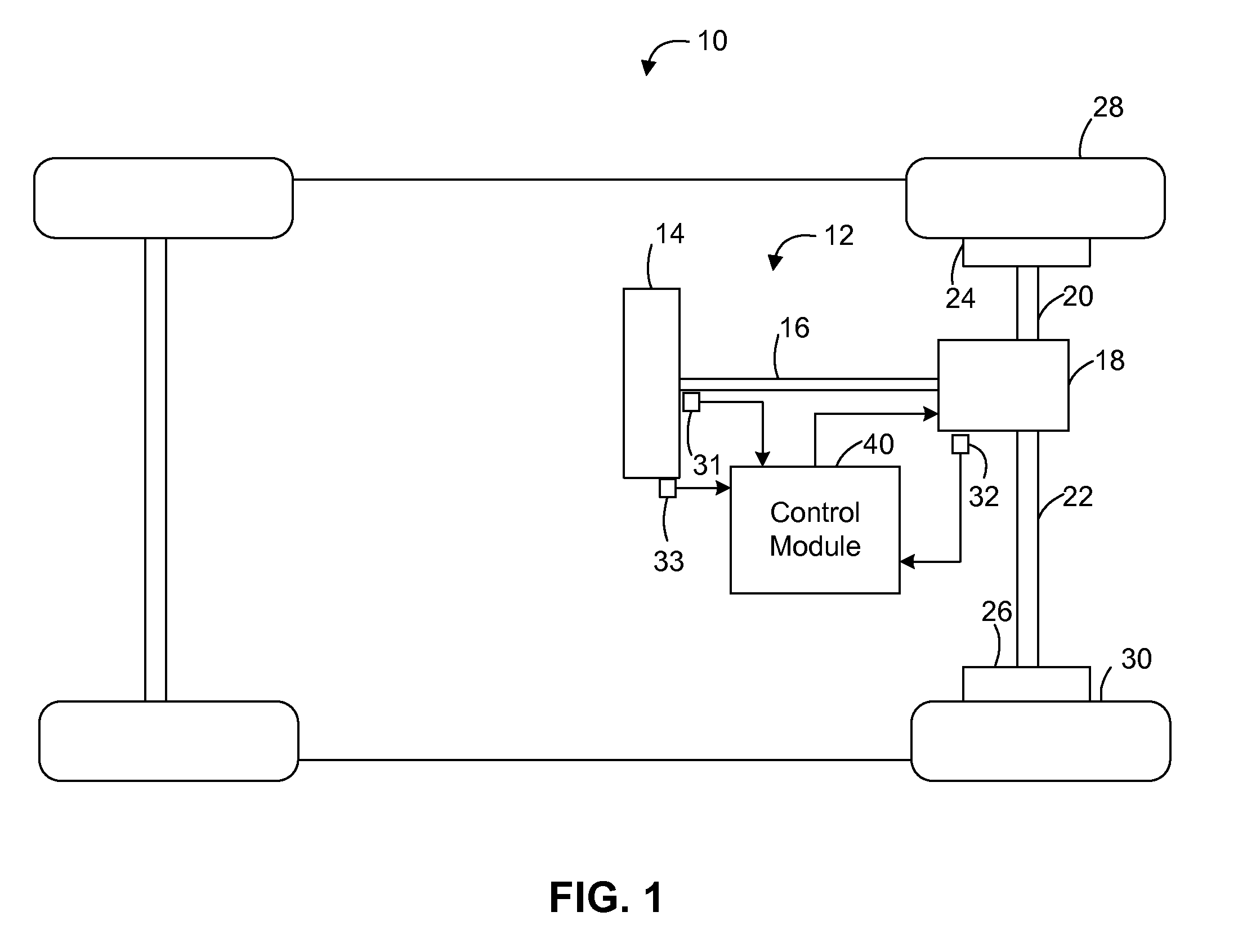
[0015]Referring now to FIG. 1, where the invention will be described with reference to specific embodiments without limiting same, a vehicle 10 including a steering system 12 is illustrated. In various embodiments, the steering system 12 includes a hand wheel 14 coupled to a steer...


PUM


Abstract

A control system for controlling a steering system is provided. The control system includes a first module that selectively determines a gain curve based on a position of a hand wheel of the steering system. A second module determines a motor assist command based on the gain curve.

Description

CROSS-REFERENCES TO RELATED APPLICATIONS[0001]This patent application is a continuation of and claims priority to U.S. patent application Ser. No. 12 / 499,527, filed Jul. 8, 2009 which is incorporated herein by reference in its entirety.FIELD[0002]The present disclosure relates to methods and system for controlling a steering system, and more particularly to methods and system for reducing end of travel harshness in a steering system.BACKGROUND[0003]The subjective impression of vehicle steering systems can be influenced by system behavior at the end of travel. A negative impression can occur if there is a harsh, abrupt feeling when steering into the corners. In some applications, a metal-on-metal clunk due to the steering rack end of travel hardware causes both audible and tactile annoyances.[0004]In present applications, the end-of-travel feel is influenced primarily by the rack-and-pinion travel stop compliance. If a deficiency in the subjective impression is found at end-of-travel...

Claims


Application Information

Patent Timeline
IPC IPC(8): G06F19/00
CPCB62D5/0469
Inventor CHAMPAGNE, ANTHONY J.
Owner STEERING SOLUTIONS IP HLDG
Why Eureka
Try Eureka