Heat exchanges for dispensing sub-zero beer

a technology of sub-zero temperature and heat exchange, which is applied in the direction of heat exchanger types, lighting and heating apparatus, stationary tubular conduit assemblies, etc., can solve the problems of high initial installation cost and high maintenance cost, and achieve the effect of eliminating or ameliorating the problem and maximising the transfer of cold

Inactive Publication Date: 2011-01-20
TEMPAK INT
View PDF6 Cites 15 Cited by
  • Summary
  • Abstract
  • Description
  • Claims
  • Application Information

AI Technical Summary

Benefits of technology

[0026]The angle provides three dimensional heat flux within the solid areas and acts as a means of inducing turbulence to the heat flow through the solid areas and maximising the available transfer of cold through the system.
[0027]The efficiency control that is available through the present invention allows for cooling of beer to precise temperatures and even temperatures close to freezing point, using direct expanded Freon refrigeration methods.
[0028]The present invention allows for a complete system including the refrigeration equipment to be packaged into a small area, such as is available under bars and dispensing counters etc., which removes the need for large installations and the associated costs and maintenance of the same.
[0029]The present invention may also eliminate or ameliorate the problems associated with freezing of subzero beverages which has limited the dispensing of low alcohol beverages at temperatures less that 0 degrees C. using existing heat exchanger systems.

Problems solved by technology

These systems have high maintenance costs associated with the external cold source and a high initial installation costs involving extensive site alterations to the beer system.

Method used


Image

  • Heat exchanges for dispensing sub-zero beer
  • Heat exchanges for dispensing sub-zero beer
  • Heat exchanges for dispensing sub-zero beer

Examples


Embodiment Construction

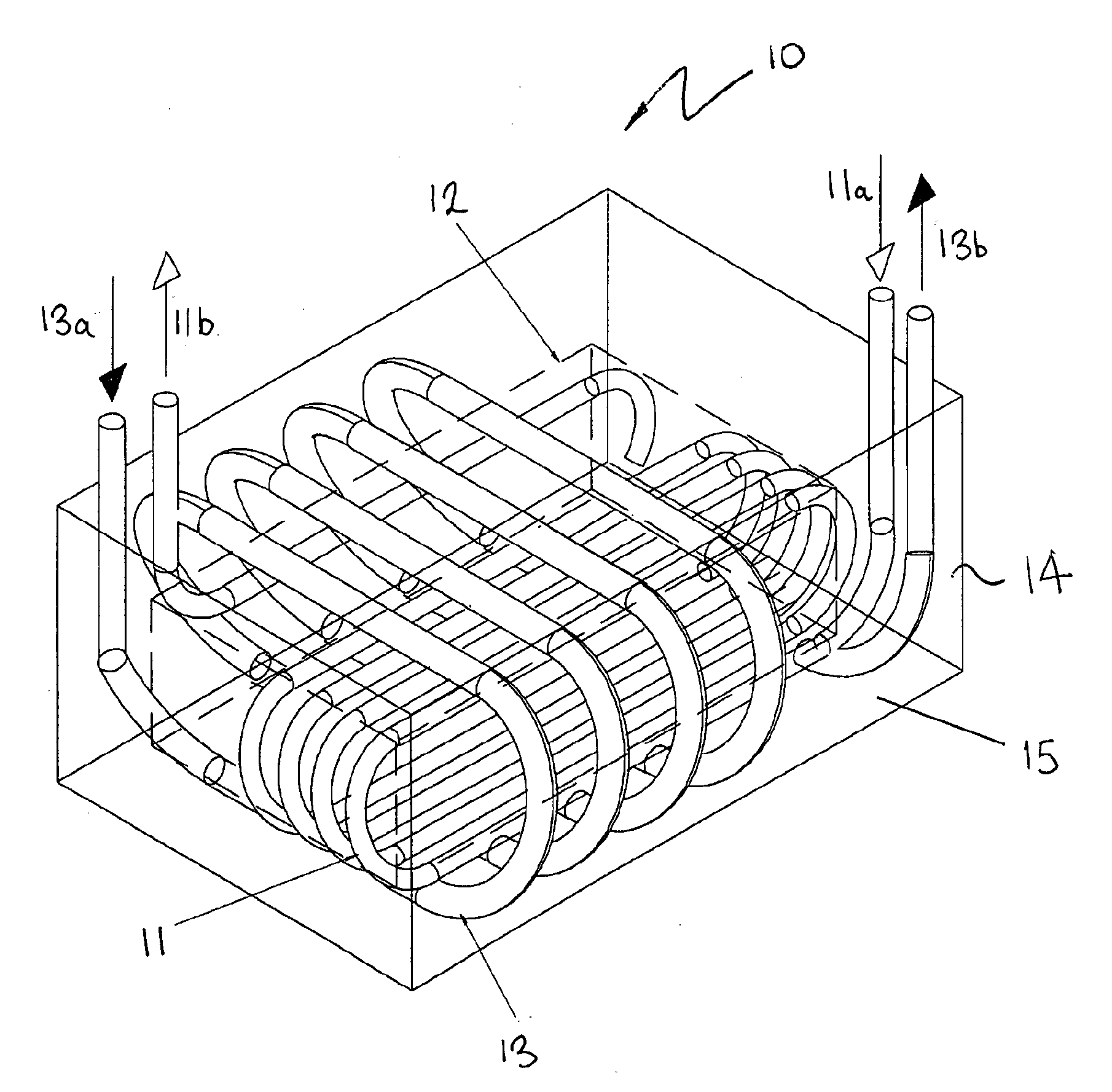
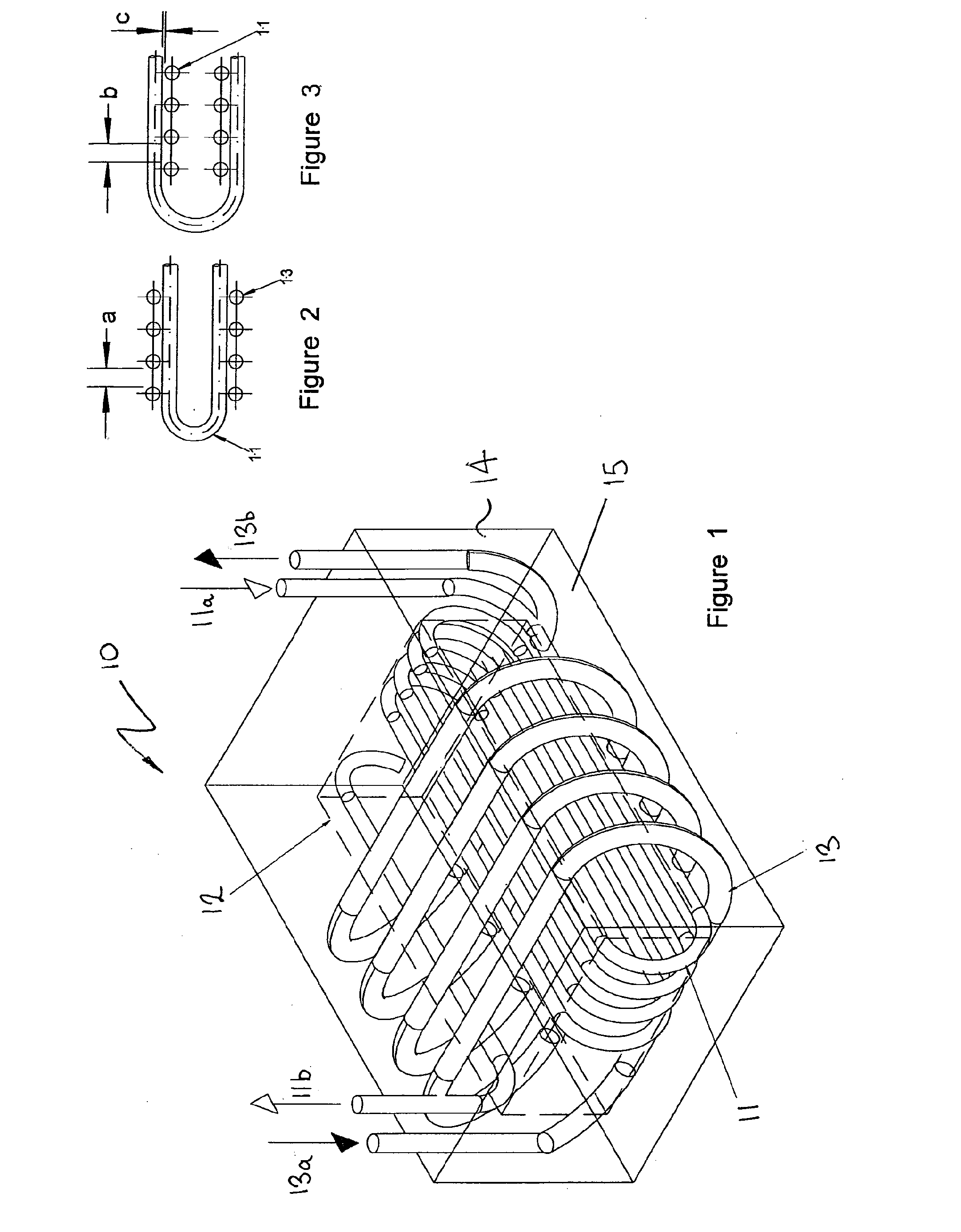
[0043]Referring to the drawings FIG. 1 shows a solid block heat exchanger 10 comprising a first coolant line or tube (typically formed from stainless steel) in the form of a “helical” coil arrangement 11 having a plurality of turns / coils. As shown the coils are generally rectangular in plan view having semi-circular curved ends separated by straight lengths of tubing. However other coil shapes could be used.

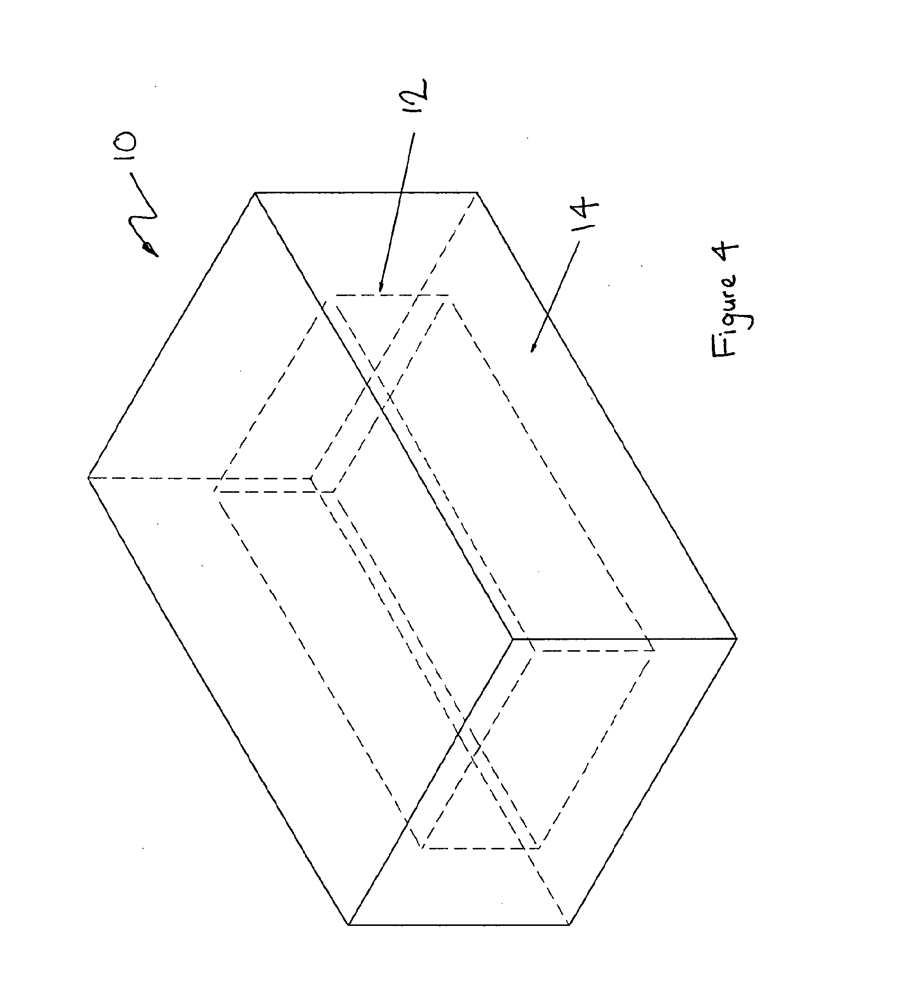
[0044]This coil arrangement locates generally within an cold zone 12 of the heat exchanger 10 within a rectangular box shaped volume also shown in FIG. 4. In this embodiment, the coil 11 is an inner coil as, extending around the outside of the coil arrangement 11 is a second “helical” coil arrangement 13 (also typically formed from stainless steel tubes) which in use carries beverage, typically beer, or other carbonated alcoholic drink of a similar alcohol content to beer.

[0045]As shown, the coils are generally rectangular in plan view having semi-circular curved ends separated b...


PUM


Abstract

A heat exchanger (10) comprises a coolant line (11) and a beverage line (13), embedded in a solid block of Aluminium (15). The coolant line (11) is in the form of a first helical coil defining a plurality of turns typically located in the centre of the block. The beverage line (13) is in the form of a second helical coil defining a plurality of turns extending around the first coil. The coolant line defines a cold zone (12), typically in the centre of the block, with the volume outside the central zone carrying the beverage line ratio defining an designated beverage cooling zone (14). The volume ratio of the designated zone to the cold zone is about 150:100. The heat exchanger allows for cooling of beer to precise temperatures and even temperatures close to freezing point, using direct expanded Freon refrigeration methods. The complete system including the refrigeration equipment to be packaged into a small area, such as is available under bars and dispensing counters etc., which removes the need for large installations and the associated costs and maintenance of the same. In a variant an additional beverage cooling zone may be located inside the cold zone. The positions of the coolant and beverage lines may also be reversed in certain applications.

Description

CROSS-REFERENCE TO RELATED APPLICATIONS[0001]The present application claims priority from Australian Provisional Patent Application No 2008900054 filed on 4 Jan. 2008, the content of which is incorporated herein by reference.FIELD OF THE INVENTION[0002]This invention relates to an improved apparatus for dispensing cooled fluids, in particular beverages, such as beer.BACKGROUND OF THE INVENTION[0003]In most commercial establishments where beer is served, the beer is supplied in barrels or kegs. The kegs are stored in a refrigerated cold room or cellar at a temperature range of between 3 and 10 degrees C. The beer is normally dispensed through beer dispensing valves / taps located away from the cold room. A heat exchanger or some form of extra cooler is also normally included in the system to further cool the beer in line between the cold room and the tap.[0004]The beer is delivered to the taps from the kegs through a conduit containing the beer delivery lines. The conduit also contains...

Claims


Application Information

Patent Timeline
Patent Type & Authority Applications(United States)
IPC IPC(8): F28D21/00
CPCF28D7/0016
Inventor BAKER, BENJAMIN PAUL
Owner TEMPAK INT
Why Eureka
Try Eureka