Methods and apparauts for an electronic drop safe

a safe and electronic technology, applied in the field of electronic safe improvement, can solve the problems of consuming a significant portion of the manager's time, requiring considerable effort to break into, and adding to the paperwork required by both cashiers, so as to achieve the effect of optimizing the business

Inactive Publication Date: 2011-01-20
ELLENBY TECH
View PDF3 Cites 11 Cited by
  • Summary
  • Abstract
  • Description
  • Claims
  • Application Information

AI Technical Summary

Benefits of technology

[0014]It is another object of the present invention to allow identification of specific cash or non cash deposits physically within the cash acceptor for later accountability even when using third party counting and pickup services.
[0023]A further object of the present invention is to provide a mechanism to allow the updating of the bill acceptor to allow new currencies, currency updates, or other firmware updates without requiring a collection.

Problems solved by technology

These safes are secure and require considerable effort to break into.
Unfortunately, the use of these drop safes adds to the paperwork required by both the cashiers and the store managers to track information associated with a deposit, such as the amount of money, cashier, shift and day, for example.
All of these tasks can consume a significant portion of the manager's time and expose the business to potentially large losses resulting from a robbery occurring while the money is being removed from the safe and counted.
The identification numbers or hot keys if incorrectly punched cause errors in identifying the source of the deposited funds.
If intentionally wrongly entered, the misidentification might be tied to employee theft.
Additionally, a considerable amount of data entry was required on the part of the manager to set up the allowed cashier identification numbers and to create end of shift reports, business day reports, and the like.
Some safes provide a second bill acceptor which is enabled when the first is full, which adds considerable cost to the safe.
In these cases, considerable expense has limited the use of the safes due to the expense of setting up the system, including wiring and configuration, the need for a computer in each facility and customized software to allow the use of the electronic safes.
Unfortunately, in the case of electronic safes, access to the bill acceptors requires a collection be made by physically opening the safe, forcing either the store manager or the armored car service to be present.

Method used


Image

  • Methods and apparauts for an electronic drop safe
  • Methods and apparauts for an electronic drop safe
  • Methods and apparauts for an electronic drop safe

Examples


Embodiment Construction

[0029]The present invention now will be described more fully with reference to the accompanying drawings, in which several presently preferred embodiments of the invention are shown. This invention may, however, be embodied in various forms and should not be construed as limited to the embodiments set forth herein. Rather, these embodiments are provided so that this disclosure will be thorough and complete, and will fully convey the scope of the invention to those skilled in the art.

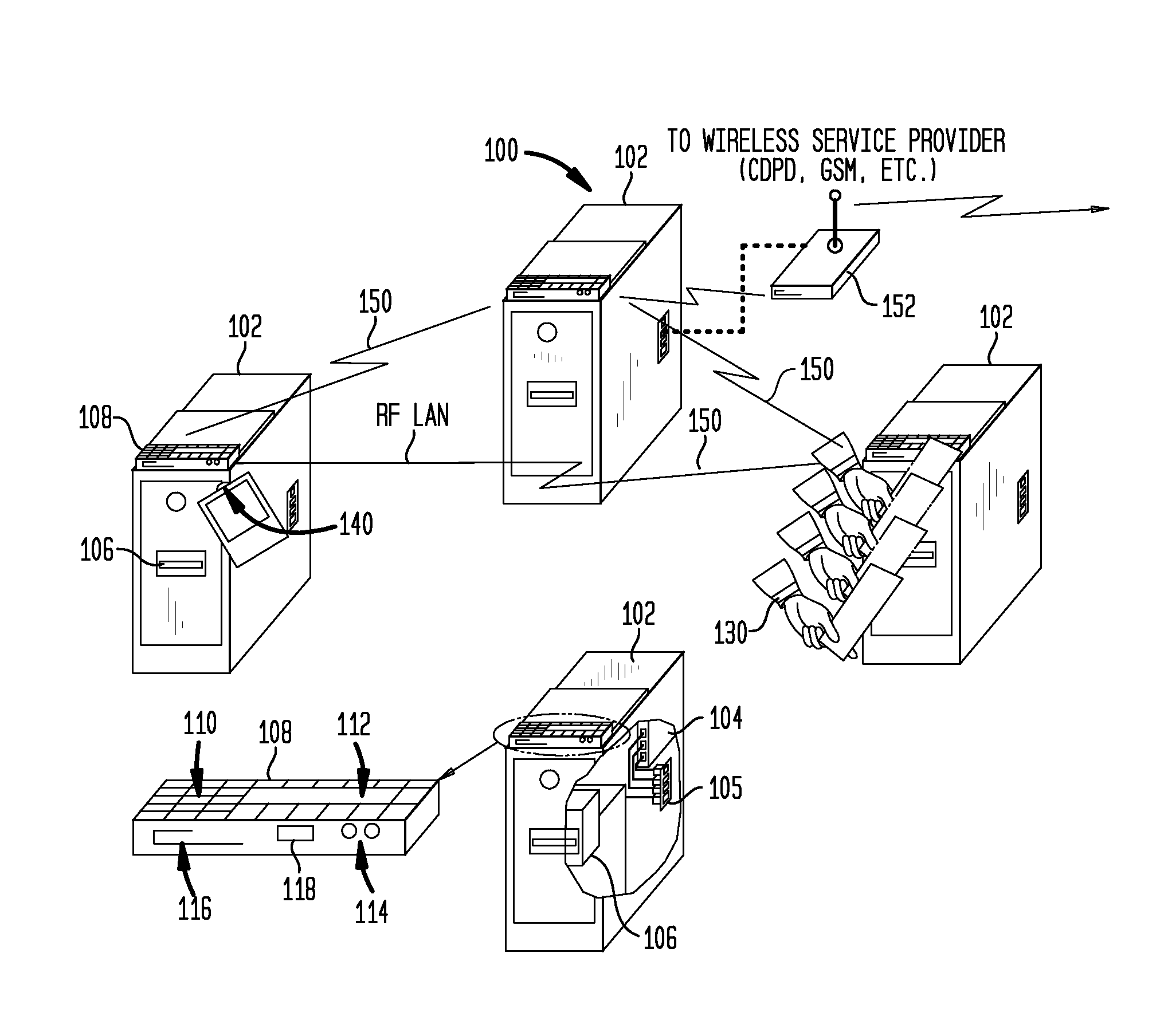
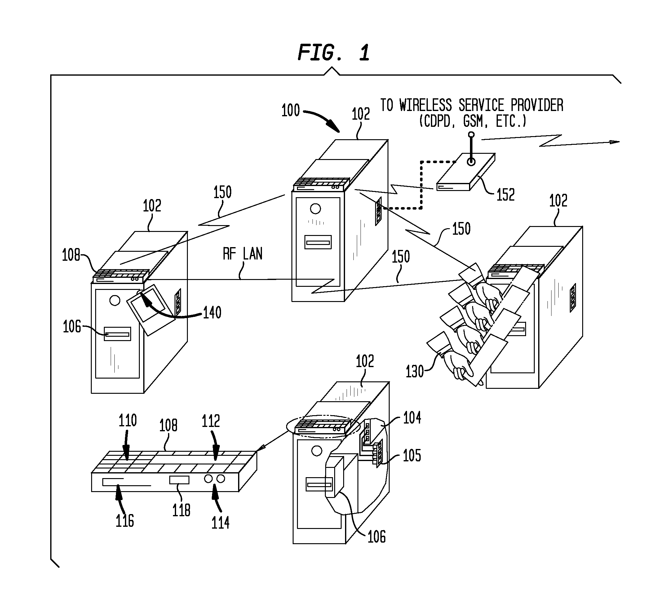
[0030]In one aspect, as shown in FIGS. 1 and 3, the present invention provides an electronic safe system 100 comprising a plurality of electronic safes 102. Each electronic safe includes a controller 104 and a bill acceptor 106 for receiving both cash and non-cash deposits. An interface module 108 may include a keypad 110, a display 112, an optical communication port 114, and a radio frequency (RF) local area network (LAN) antenna 116, and an RF identification tag antenna 118. The controller module 104 c...


PUM


Abstract

Systems and techniques for providing an improved electronic safe are described. In one aspect, an electronic safe is provided with enhanced security, increased functionality and ease of use. The electronic safe may accept both cash and non-cash deposits, identifying tags and envelopes or folders. A wireless tag may be used to identify the person making deposits. A plurality of electronic safes may be networked together in a wireless local area network. The wireless local area network of electronic safes may be wirelessly networked with an off site host system. In another aspect, an electronic safe is provided with a wireless communications link for communicating with a handheld terminal which may be used to update the electronic safe and initiate the generation of automatic reports. In another aspect, an electronic safe automatically generates reports detailing the operation of the safe. The electronic safe may predict the time when a cassette for storing deposits will be full.

Description

CROSS-REFERENCE TO RELATED APPLICATION[0001]The present application is a divisional of U.S. application Ser. No. 11 / 474,206 filed Jun. 23, 2006 which is a divisional of U.S. application Ser. No. 09 / 960,595 filed Sept. 21, 2001 which in turn claims the benefit of U.S. Provisional Application Ser. No. 60 / 234,133 entitled “Methods and Apparatus for an Electronic Drop Safe” filed Sept. 21, 2000.FIELD OF THE INVENTION[0002]The present invention relates generally to improvements in electronic safes. More particularly, the present invention relates to improvements in electronic safes that provide for enhanced security, increased functionality and ease of use.BACKGROUND OF THE INVENTION[0003]Many retail businesses commonly have at least one drop safe on site. Particularly in high cash flow transaction businesses, cashiers are required to limit the amount of cash stored in the cash drawers to a predetermined amount. Any excess cash is placed in a secure drop safe to secure the cash from pote...

Claims


Application Information

Patent Timeline
Patent Type & Authority Applications(United States)
IPC IPC(8): G07D11/00E05G7/00G06Q20/20
CPCE05G7/001G07D11/0096G07D11/0093G06Q20/202
Inventor DOBBINS, BOB M.
Owner ELLENBY TECH
Why Eureka
Try Eureka