
Item storage and tracking system

Active Publication Date: 2011-01-20
BUILDINGLINK COM
View PDF102 Cites 13 Cited by
  • Summary
  • Abstract
  • Description
  • Claims
  • Application Information

AI Technical Summary

Benefits of technology

[0016]Another object of the present invention is to provide an item storage system that is easy to operate by an end user, size-customizable, and functionally programmable.
[0018]According to an aspect of the present invention a storage facility that does not include a programmable subcontroller may be operatively connected to the subcontroller of the first storage facility whereby the storage capacity of the system may be increased.

Problems solved by technology

The tracking of keys that open doors of apartments or cars, remains a challenge.
Marking keys with identifying information reduces security, such as when keys are removed from a cabinet and circulating.
Furthermore, in the event of a malfunction (e.g. a short) the whole panel must be replaced, which is expensive, and, with a single panel it is difficult to vary the spacing to accommodate objects of different size.
The drawback to using a grid-type arrangement is that the number of slots for receiving tags is fixed.
However, the number of slots cannot be expanded without devising a new panel.
It is, however, problematic to get accurate RFID readings of keys present / keys removed in an open field with a drawer open without getting false positives or false negatives of keys removed but nearby.
Thus, for example, when a few keys are removed and a few keys are returned at the same time the algorithm will have a difficult time to determine which key was returned and which key was taken.
The use of this complicated algorithm is necessary because the individual slots are not wired to read the unique IDs of the inserted assemblies, and thus can not determine and report on the location of a specific key assembly directly.
In addition, none of the known systems that utilize multiple RFID tags can be read both when a cabinet is open and when closed, and none enable RFID tags to be read using only a single reader and antenna without having to prewire each slot with its own antenna.
The reason for this lies in the limitations of precision for RFID tags and readers.
It is problematic to have a precise reading field whereby none of the tags that are in the box are “missed”, and whereby none of the tags that may be located immediately outside of the box or within a few inches are picked up by the readers and marked present.
Further, passive tags, typically, require a better “coupling” with the field generated by the reader, and are more prone to false negatives (undetected tags which are present).
Active tags, which are self-powered, produce stronger signals independent of the reader's generated field, and are more prone to false positives (reading a tag that has been removed) since their signals can typically travel as far as five feet.
Regardless, a known problem with any RFID reader / tag system for tracking purposes is that it requires careful placement and alignment of readers, tags and antennas in order to end up as close to the middle of the false positive-false negative continuum, and even then one is not immune to a certain amount of both error types when working within small distances and around metallic objects.

Method used


Image

  • Item storage and tracking system
  • Item storage and tracking system
  • Item storage and tracking system

Examples


Embodiment Construction

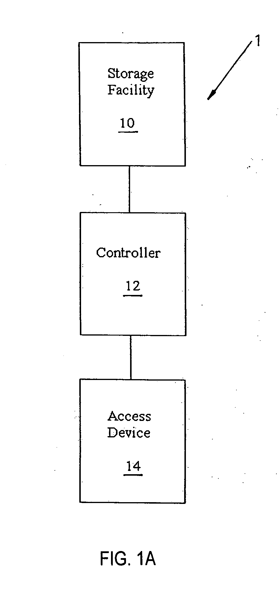
[0083]Referring to FIG. 1A, an item storage and tracking system 1 according to the present invention includes a storage facility 10 for the physical storage and housing of items that are to be securely stored and tracked. Storage facility 10 includes an electronic tracking and identification facility for the electronic tracking and identification of items stored therein, which communicates with a controller 12. Controller 12 is preferably a general purpose computer (e.g. a personal computer or PC) which is programmed to receive data from and send data and / or instructions to the electronic tracking and identification facility in storage facility 10. System 1 would further include an access device 14 such as a keyboard or the like, which can be used to provide data and / or instructions to controller 12.

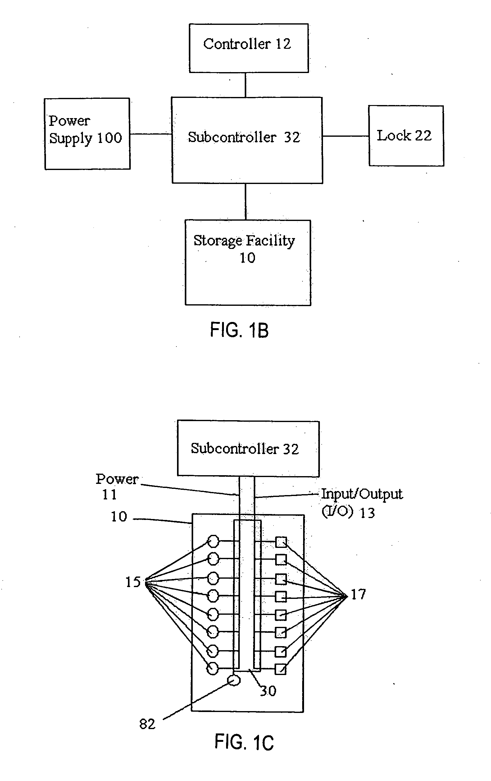
[0084]Referring now to FIG. 1B, the communication between controller 12 and storage facility 10 is preferably enabled by a subcontroller 32 which electronically communicates with control...


PUM


Abstract

An item storage facility that includes a resident programmable subcontroller, at least one stand, a one circuit board having a plurality of elongated openings therein supported on the stand, and a plurality of connectors resident on the circuit board and in communication with the subcontroller.

Description

CROSS REFERENCE TO RELATED APPLICATIONS[0001]This application is based on and claims benefit of U.S. Provisional Application Ser. No. 61 / 187,046, filed Jun. 15, 2009, entitled ITEM STORAGE AND TRACKING SYSTEM and U.S. Provisional Application Ser. No. 61 / 293,976, filed Jan. 11, 2010, entitled ITEM STORAGE AND TRACKING SYSTEM. A claim of priority is hereby made to the above applications and the contents of the above applications are specifically incorporated herein by reference.BACKGROUND OF THE INVENTION[0002]The present invention relates to a system for the tracking, the securing, and the identification of objects such as keys.[0003]The tracking of keys that open doors of apartments or cars, remains a challenge.[0004]In one known solution, a large number of keys are secured in a locked cabinet, and a computer system interfaces with the cabinet to keep records as to what is kept in the cabinet, who accesses the cabinet, which keys have been withdrawn, and which keys have been returne...

Claims


Application Information

Patent Timeline
IPC IPC(8): G08B13/14G06K5/00H05K7/00
CPCG06K17/00G06K2017/0051G06K2017/0045
Inventor KESTENBAUM, JERRY
Owner BUILDINGLINK COM
Features
  • Generate Ideas
  • Intellectual Property
  • Life Sciences
  • Materials
  • Tech Scout
  • Unparalleled Data Quality
  • Higher Quality Content
  • 60% Fewer Hallucinations
Learn More