Optical touch screen device

Inactive Publication Date: 2011-01-20
HON HAI PRECISION IND CO LTD
View PDF5 Cites 7 Cited by
  • Summary
  • Abstract
  • Description
  • Claims
  • Application Information

AI Technical Summary

Problems solved by technology

However, such arrangement inevitably increases the thickne

Method used


Image

  • Optical touch screen device
  • Optical touch screen device
  • Optical touch screen device

Examples


Example

[0013]Various embodiments will now be described in detail below with reference to the drawings.

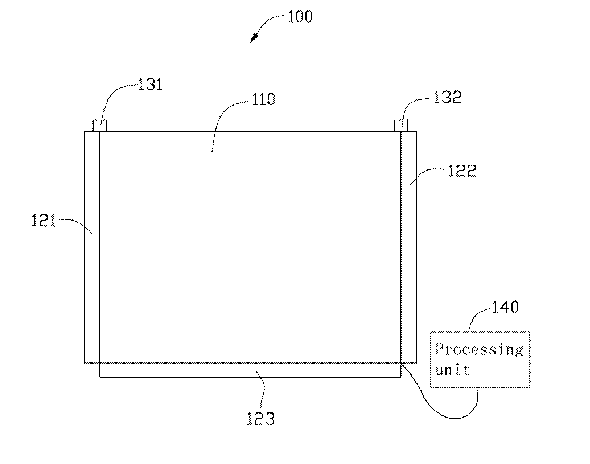
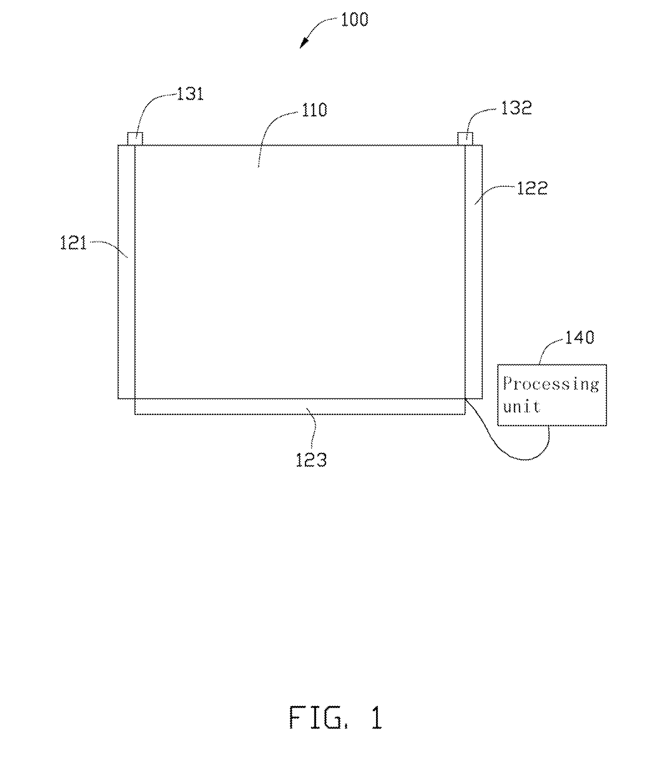
[0014]Referring to FIG. 1, an optical touch screen device 100 in accordance with a first exemplary embodiment includes a display screen 110, a first infrared (IR) sensor 121, a second IR sensor 122, a third IR sensor 123, a first IR source 131, a second IR source 132, and a processing unit 140.

[0015]In this embodiment, the display screen 110 is rectangular. The display screen 110 can be selected from the group consisting of a liquid crystal display screen, a field emission display screen and a plasma display screen.

[0016]The first, second and third IR sensors 121, 122, 123 are linear IR sensors for detecting IR light, but can be linear charge coupled devices, or linear complementary metal oxide semiconductors. The first, second, and third IR sensors 121, 122, and 123 are adjacent three sides of the display screen 110, respectively. The first, second, and third IR sensors 121, 122, 123 each...


PUM


Abstract

An optical touch screen device includes a display screen, a number of infrared sensors, two infrared sources, and a processing unit. The display screen has N sides, wherein N represents an integer greater than two. The number of infrared sensors is N−1. The N−1 infrared sensors are arranged adjacent N−1 sides of the display screen, respectively. The two infrared light sources are arranged at the remaining side such that light emitted from each of the two infrared sources cover the entire display screen and reaches the infrared sensors. The N−1 infrared sensors are configured for detecting locations of the shadows of an input device formed thereon and generating signals associated with the locations of the shadows. The processing unit is electrically connected to the infrared sensors for processing the signals to calculate a location of an input device on the surface of the display screen.

Description

BACKGROUND[0001]1. Technical Field[0002]The present disclosure relates to an optical touch screen device.[0003]2. Description of Related Art[0004]A touch panel incorporated into a thin film transistor (TFT) liquid crystal display (LCD) has been proposed. A typical LCD includes a pair of glass plates which are separated by a layer of liquid crystal material. Commonly, the touch panel can be selected from a resistive touch panel and a capacitive touch panel.[0005]In the above-described LCD, the touch panel is usually attached to a display screen of the LCD. However, such arrangement inevitably increases the thickness of the LCD. Furthermore, luminance of the LCD may suffer.[0006]Therefore, an optical touch screen device which can overcome the above-mentioned problems is desired.BRIEF DESCRIPTION OF THE DRAWINGS[0007]Many aspects of the present embodiments can be better understood with reference to the following drawings. The components in the drawings are not necessarily drawn to scal...

Claims


Application Information

Patent Timeline
IPC IPC(8): G06F3/042
CPCG06F3/0428
Inventor LEE, CHUN-YU
Owner HON HAI PRECISION IND CO LTD
Why Eureka
Try Eureka