MEMS hierarchically-dimensioned deformable mirror

a microelectromechanical system and mirror technology, applied in the field of adaptive optics, can solve the problems of less than 1000 actuators at relative slow speed, large stroke deformable minor systems using mems actuators, and not yet demonstrated sufficient attractive combinations of high stroke, low voltage, and high system reliability. , the effect of improving system reliability

Inactive Publication Date: 2011-01-20
WU XINGTAO
View PDF2 Cites 27 Cited by
  • Summary
  • Abstract
  • Description
  • Claims
  • Application Information

AI Technical Summary

Benefits of technology

The invention is about creating a reliable and durable deformable mirror system using relaxor ferroelectric single crystals and other materials like silicon. The goal is to create a material system that can operate for a long time without failure.

Problems solved by technology

The technical problem addressed in this patent is the need for a deformable minor that can offer high performance wavefront correction in the presence of fluctuating media like atmospheric turbulence, while being cost-effective, lightweight, and reliable. The current conventional deformable minors tend to be bulky, heavy, expensive, and operate with less than 1000 actuators at relative slow speed. The use of MEMS-based deformable mirrors has been successful in small stroke applications but not in large stroke applications with high reliability requirements. The patent describes a new design that offers higher actuation force and stroke while being simpler and more efficient in manufacturing.

Method used


Image

  • MEMS hierarchically-dimensioned deformable mirror
  • MEMS hierarchically-dimensioned deformable mirror
  • MEMS hierarchically-dimensioned deformable mirror

Examples


Embodiment Construction

[0027]To provide an overall understanding of the invention, certain illustrative embodiments will now be described, including actuators and methods for controlling deformable minors. However, it will be understood by one of ordinary skill in the art that the systems and methods described herein may be adapted and modified as is appropriate for the application being addressed and that the devices and methods described herein may be employed in other suitable applications, and that such other additions and modifications will not depart from the scope hereof.

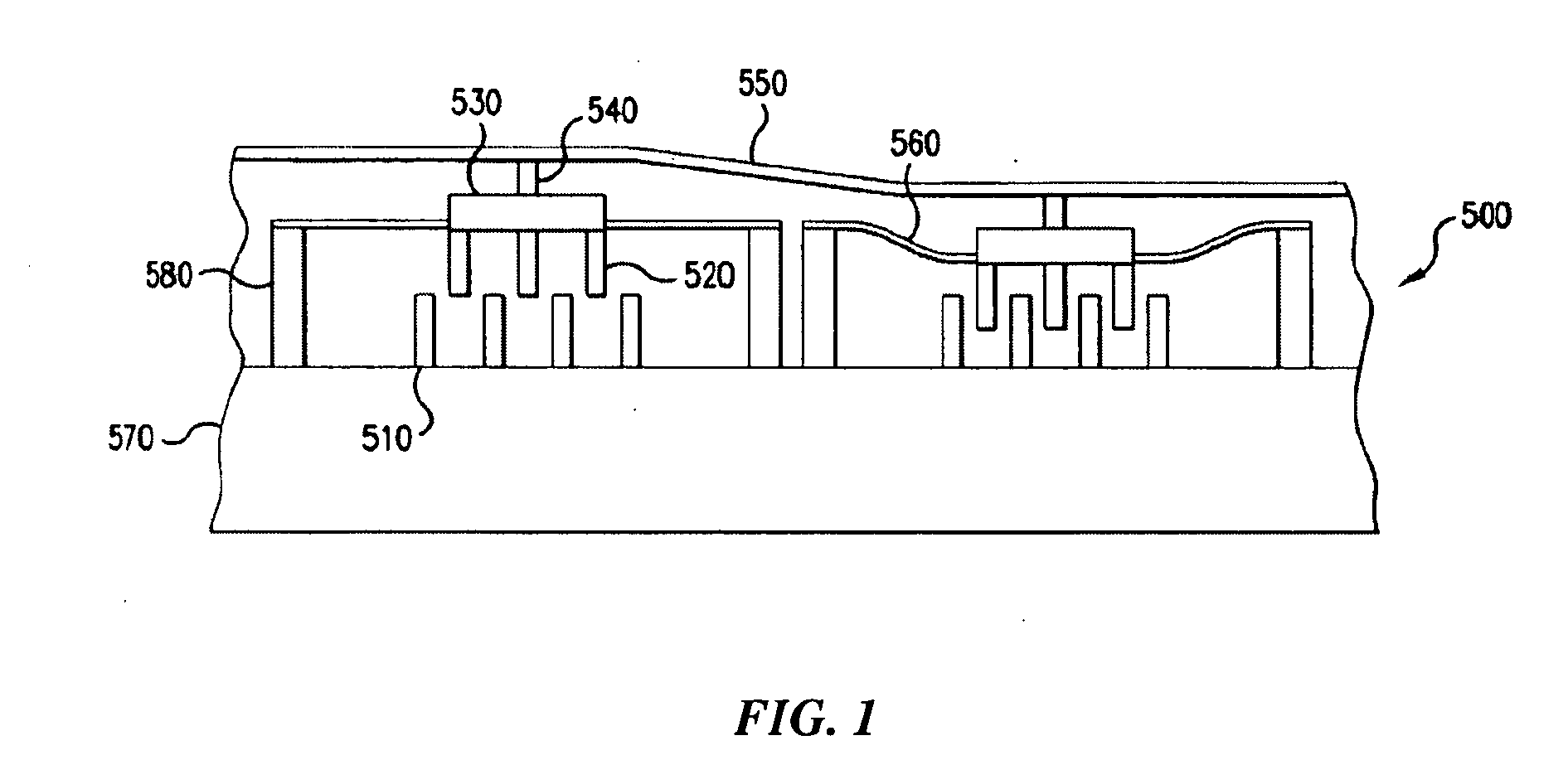
[0028]As discussed in the Background section above, prior art MEMS deformable mirror membrane 550, FIG. 1 (see U.S. Pat. No. 6,384,952) is equipped with electrostatic comb actuators 500. The actuators 500 include stator 510 and sliders 520. The sliders 520 are integrated with a slider top 530. Posts 540 attach the slider 520 via the slider top 530 to the deformable minor membrane 550. Each post 540 will pull on the minor 550 with t...


PUM


Abstract

A MEMS hierarchically-dimensioned deformable minor comprising a substrate, a plurality of spacers disposed on the substrate, a plurality of piezoelectric cantilever microactuators disposed on the plurality of spacers, and a continuous deformable membrane disposed on the plurality of the cantilever assemblies, has significantly improved overall device performances owing to the use of the cantilever microactuators based on relaxor ferroelectric single crystal materials or other piezoelectric materials.

Description


Claims


Application Information

Patent Timeline
Owner WU XINGTAO
Why Eureka
Try Eureka