Color electrophotographic image forming apparatus

Active Publication Date: 2011-01-20
CANON KK
View PDF3 Cites 2 Cited by
  • Summary
  • Abstract
  • Description
  • Claims
  • Application Information

AI Technical Summary

Problems solved by technology

However, in late years the main body of device is getting downsized and the size of the rotary support is also becoming smaller in accordance with the downsizing.
Thus, if the main body is downsized, the detected error of the phase of the rotary support by the

Method used


Image

  • Color electrophotographic image forming apparatus
  • Color electrophotographic image forming apparatus
  • Color electrophotographic image forming apparatus

Examples


first embodiment

Color Electrophotographic Image Forming Apparatus

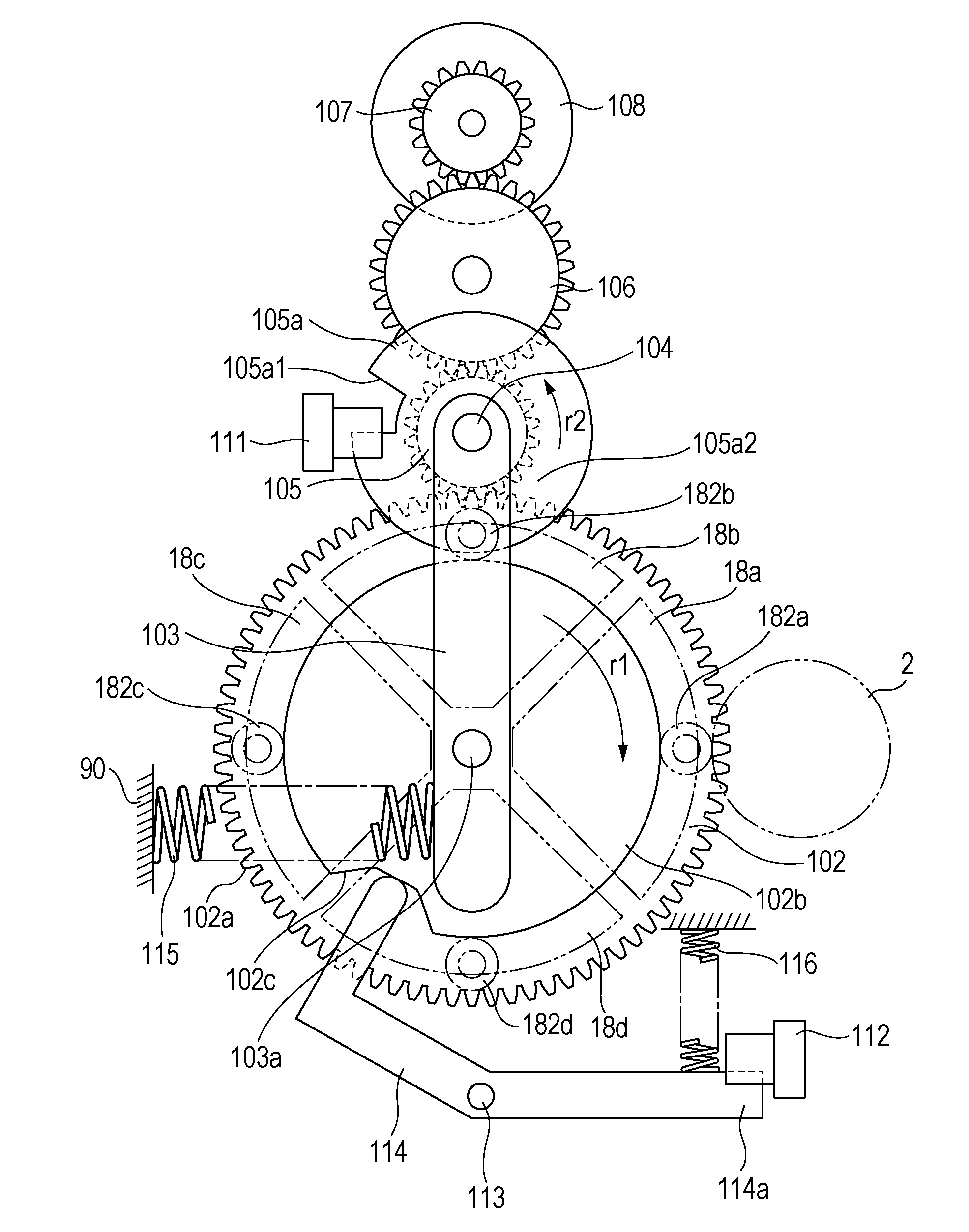
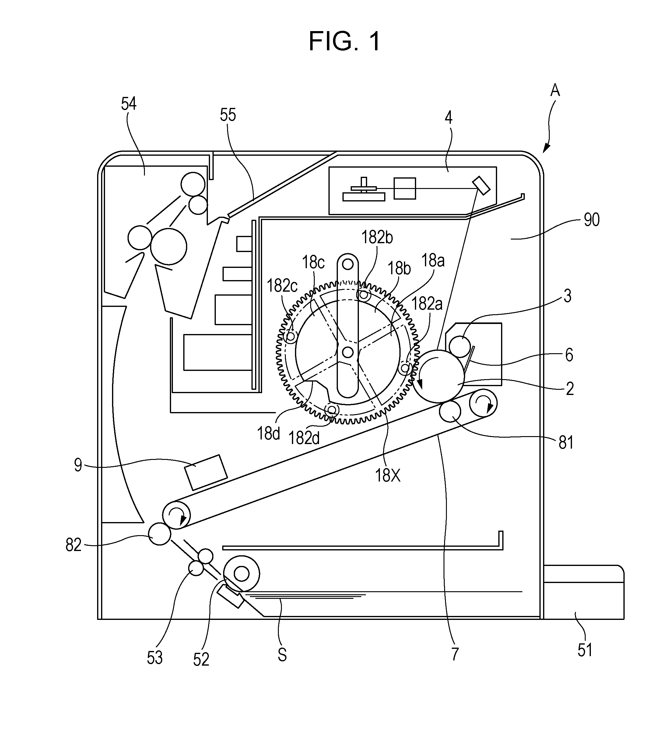
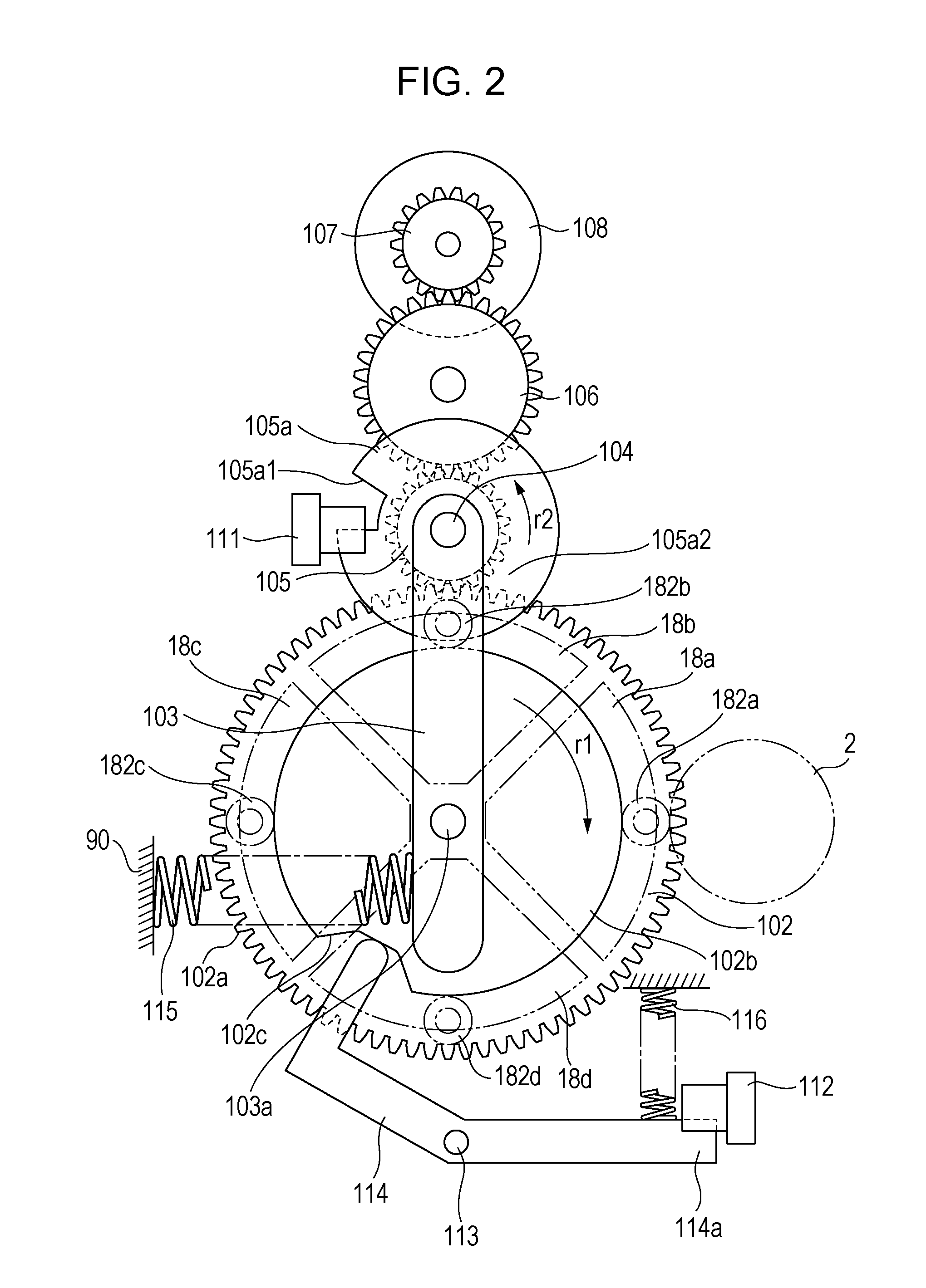
[0022]Color electrophotographic image forming apparatus concerning Example 1 will be described. Herein, as a color electrophotographic image forming apparatus, the color laser beam printer comprising four developing devices is exemplified. FIG. 1 is a sectional view of the color laser beam printer.

[0023]First, image forming operation of this color laser beam printer will be described.

[0024]As shown in FIG. 1, image forming apparatus A comprises electrophotographic photosensitive drum (explained as electrophotosensitive drum below) 2. Around electrophotosensitive drum 2, charging roller 3, exposure device 4, four developing devices 18a-18d and cleaning device 6 are located. Charging roller 3 corresponds to charging means for charging electrophotosensitive drum 2 equally. Exposure device 4 corresponds to exposure means to irradiate electrophotosensitive drum 2 with a laser beam depending on image information. Electrophotographic latent ...

second embodiment

[0055]A figure which extracts a rotary part of a color laser beam printer comprising Embodiment 2 is shown in FIG. 8-FIG. 9. FIG. 8 is a front view and FIG. 9 is a top view.

[0056]The present embodiment performed detection of plate 105a and detective arm 114 only be sensor 111 compared to embodiment 1. Thus, as well as an effect of embodiment 1, there is a benefit that it is possible to omit one sensor.

[0057]Idler gear 105 makes a similar operation as embodiment 1. And the number of the teeth of gear part 102a is a multiple of natural number n of idler gear 105. Here, it is assumed as 4 times for the convenience of explanation. Plate 105a comprises shading department 105a1 shading optical path L1 of detective light as well as embodiment 1 and opening unit 105a2 which is a notch unit opening optical light L1. Detection lever 114 is rotatably supported by drive shaft 104. Shading part 114a which can shade the light in optical path L1 of the detective light is comprised in one end of de...


PUM


Abstract

An apparatus, which able to stop with accuracy rotary support which supports plurality of developing devices, is provided. When rotary support rotates once, phase detecting device rotates multiple number n times, and color detecting flag shades or passes color detecting sensor when rotary support is in the predetermined phase. The number is a nature number.

Description

CROSS REFERENCE TO RELATED APPLICATIONS[0001]This application is a Continuation of International Application No. PCT / JP2009 / 061736, filed Jun. 26, 2009, which is hereby incorporated by reference herein in its entirety.BACKGROUND OF THE INVENTION[0002]1. Field of the Invention[0003]The present invention relates to a color electrophotographic image forming apparatus using a rotatable rotary support in support of a plurality of developing devices.[0004]2. Description of the Related Art[0005]Conventionally, a color electrophotographic image forming apparatus using a rotatable rotary support (rotary) supporting a plurality of developing devices has been known in the art. In the image forming apparatus, by rotating the rotary support, a plurality of developing devices supporting the rotary support are moved sequentially to the developing position opposed to an electrophotosensitive drum. The color electrophotographic image forming apparatus provides a sensor flag to the rotary support as ...

Claims


Application Information

Patent Timeline
IPC IPC(8): G03G15/01
CPCG03G15/0896G03G15/0173G03G2215/0177G03G15/01G03G15/06
Inventor AOKI, DAISUKE
Owner CANON KK
Why Eureka
Try Eureka