
Navigation system, navigation device, navigation server, vehicle provided with a navigation device, group of such vehicles and navigation method

a navigation system and navigation server technology, applied in the field of navigation systems, can solve the problems of increasing the distance between the satellite signal and the navigation solution, the accuracy improvement is relatively small, and the navigation solution becomes useless within minutes, etc., to achieve the effect of improving the estimation accuracy, reducing the distance, and increasing the radius

Inactive Publication Date: 2014-04-15
NEDERLANDSE ORG VOOR TOEGEPAST NATUURWETENSCHAPPELIJK ONDERZOEK TNO
View PDF8 Cites 2 Cited by
  • Summary
  • Abstract
  • Description
  • Claims
  • Application Information

AI Technical Summary

Benefits of technology

[0067]Two navigation devices are considered to be in each others proximity if they are within a predetermined range with respect to each other. The predetermined range depends on the required accuracy and on the practical means that are used to detect the encounter. For example the predetermined range may coincide with the detection range of an RFID detector. The predetermined range may for example be a sphere having a predetermined radius. Any object within that sphere will be considered as being within the predetermined range. Said predetermined radius may for example be in the order of 50 cm to 10 meter. With a substantially smaller radius, e.g. 10 cm, the probability that two vehicles spontaneously encounter each other is relatively small. Therewith also the amount of information that can be exchanged and that can be used to improve the estimation accuracy is small. However, in case that deliberate encounters between the vehicles are arranged, this is not a problem. In that case the detection radius may be relatively small if desired. If the radius is much larger than 10 m, e.g. 50 m, the accuracy improvement is relatively small. Also situations are possible wherein a substantially larger radius may be acceptable. A submarine vessel having an accuracy of 1% will have a navigation error of 1 km after a travelled distance of 100 km. In that case an encounter with another submarine vessel also having a navigation device at a distance of 100 m may still be considered as proximate. It is true that an error is made by assuming that the navigation devices of the two encountering submarine vessels are at the same position, and consequently this error will also cause an error in the estimation of the bias factors of the navigation systems. However, as the error (100 m) made in this assumption is substantially smaller than the practically occurring navigation errors (1 km), still a more accurate estimation of the bias factors is obtained, therewith improving navigation accuracy. Likewise, navigating robots in a building may have a navigation error incrementing to tens of meters. In that case a distance of some meters may be considered proximate. It is sufficient that

Problems solved by technology

However, in some circumstances alternative navigation methods are required as satellite signals required for GPS-navigation are not always available, for example at locations below sea level and in buildings.
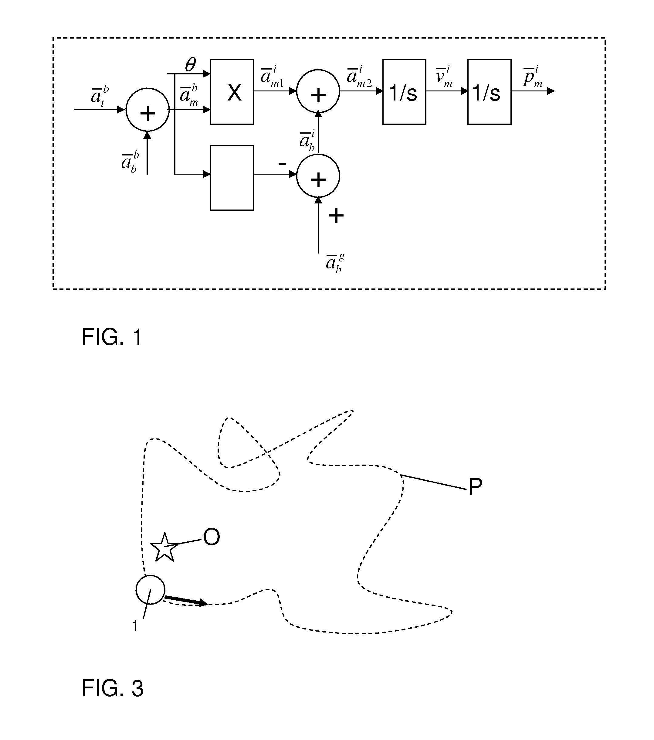
Generally accelerometers have a systematic error, also denoted as bias, resulting in a drift in position indication, exponential in time.
With low-cost sensors, and without bias compensation, the navigation solution becomes useless within minutes.
In case navigation on the basis of inertial sensing, inaccuracies result from a bias in the measured acceleration.
The latter bias is due to imperfections of the gyroscopes, internal alignment errors in the navigation device and orientation initialization errors of the navigation device.

Method used


Image

  • Navigation system, navigation device, navigation server, vehicle provided with a navigation device, group of such vehicles and navigation method
  • Navigation system, navigation device, navigation server, vehicle provided with a navigation device, group of such vehicles and navigation method
  • Navigation system, navigation device, navigation server, vehicle provided with a navigation device, group of such vehicles and navigation method

Examples


Embodiment Construction

[0089]In the following detailed description numerous specific details are set forth in order to provide a thorough understanding of the present invention. However, it will be understood by one skilled in the art that the present invention may be practiced without these specific details. In other instances, well known methods, procedures, and components have not been described in detail so as not to obscure aspects of the present invention.

[0090]The invention is described more fully hereinafter with reference to the accompanying drawings, in which embodiments of the invention are shown. This invention may, however, be embodied in many different forms and should not be construed as limited to the embodiments set forth herein. Rather, these embodiments are provided so that this disclosure will be thorough and complete, and will fully convey the scope of the invention to those skilled in the art. In the drawings, the size and relative sizes of layers and regions may be exaggerated for c...


PUM


Abstract

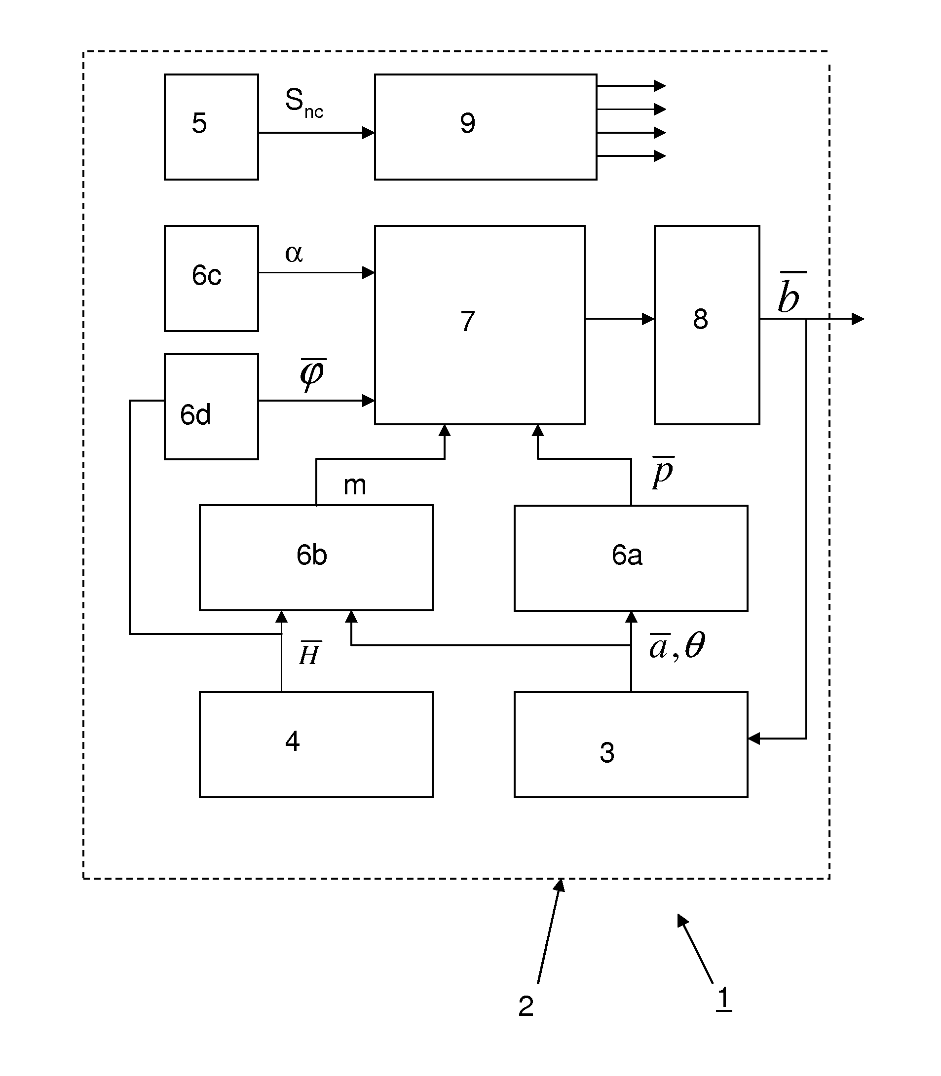
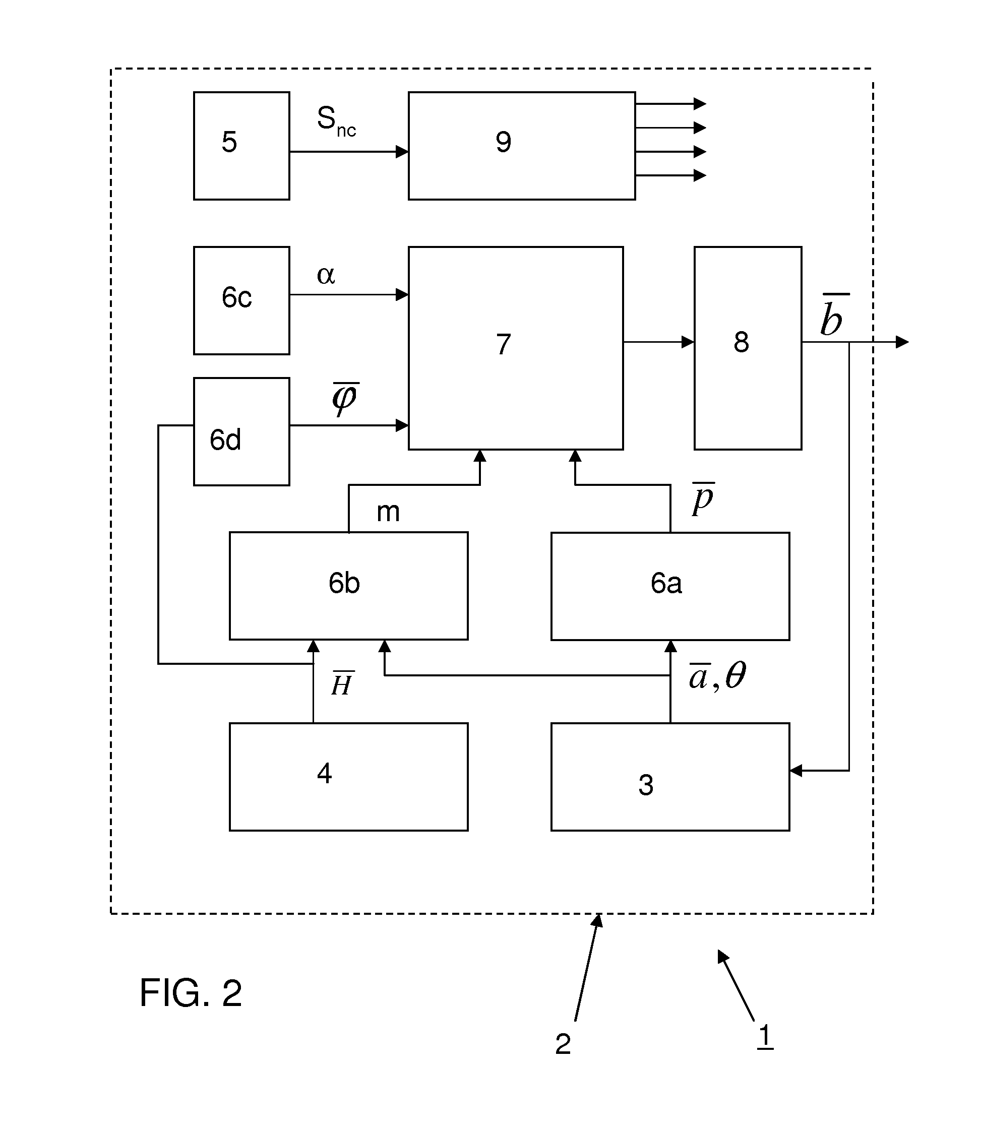
A navigation system is disclosed comprising a navigation device (2a) with a navigation sensor unit (3) and a magnetic field sensor unit (4), the navigation device is arranged to be moved. The navigation sensor unit (3) is arranged for providing a navigation signal with navigation information (ā, θ). The magnetic field sensor unit is arranged for providing a magnetic field signal (H) indicative for a magnetic field strength. The navigation system further comprises a first integration unit (6a) for integrating the navigation signal (ā, θ) and for providing a first integration result (p), a second integration unit (6b) for calculating a path-integral of the magnetic field signal using the navigation signal, and for providing a second integration result (m), a first auxiliary integration unit (6c) for providing a first coefficient (α), a second auxiliary integration unit (6d) for providing a second coefficient (φ), and a proximity detector (5) for providing a proximity signal (Snc) indicative whether a distance between the navigation device (2a) and a reference position is less than a predetermined value. A matrix solving unit (8) for solves a set of equations based on the first integration result, the second integration result, the first coefficient and the second coefficient.

Description

BACKGROUND[0001]1. Field of the Invention[0002]The present invention relates to a navigation system.[0003]The present invention further relates to a navigation device.[0004]The present invention further relates to a navigation server.[0005]The present invention further relates to a vehicle provided with a navigation device.[0006]The present invention further relates to a group of such vehicles.[0007]The present invention relates to a navigation method.[0008]2. Related Art[0009]Nowadays GPS navigation facilities are available that can relatively accurate determine a position of a vehicle. However, in some circumstances alternative navigation methods are required as satellite signals required for GPS-navigation are not always available, for example at locations below sea level and in buildings. One such alternative method applies dead-reckoning using data obtained from odometers or inertial sensors, for instance gyroscopes and accelerometers. Gyroscopes provide information about the o...

Claims


Application Information

Patent Timeline
Patent Type & Authority Patents(United States)
IPC IPC(8): G01C21/08
CPCG01C21/165G01C21/1654
Inventor RUIZENAAR, MARCEL GREGORIUS ANTHONIUS
Owner NEDERLANDSE ORG VOOR TOEGEPAST NATUURWETENSCHAPPELIJK ONDERZOEK TNO
Learn More