
Hydraulic element

a technology of water elements and components, applied in the field of water elements, can solve the problems of complex assemblage and many components of parts, and achieve the effect of simple design and low accuracy requirements

Active Publication Date: 2011-11-08
LUK VERMOGENSVERW MBH
View PDF9 Cites 0 Cited by
  • Summary
  • Abstract
  • Description
  • Claims
  • Application Information

AI Technical Summary

Benefits of technology

"The present invention provides a simple design for a hydraulic element, which can be manufactured with little accuracy requirements. The hydraulic element includes a valve arrangement with two valve bodies that can be displaced relative to each other against a spring force. The valve arrangement features an external valve body and an internal valve body, which can be brought to overlap their connection holes. The external valve body and the internal valve body prevent rotation in opposite directions, ensuring the valves cannot be brought to overlap. The internal valve body also has a valve head that forms a valve seat with the housing, creating different flow resistances in the two flow directions. The housing also has a clutch assembly on one side. The present invention provides a hydraulic clutch operation system with a master cylinder, a slave cylinder, and a pressure line connecting them, wherein a hydraulic element according to the invention is disposed."

Problems solved by technology

Such a part consists of many components and is complicated in assemblage.

Method used


Image

  • Hydraulic element
  • Hydraulic element
  • Hydraulic element

Examples


Embodiment Construction

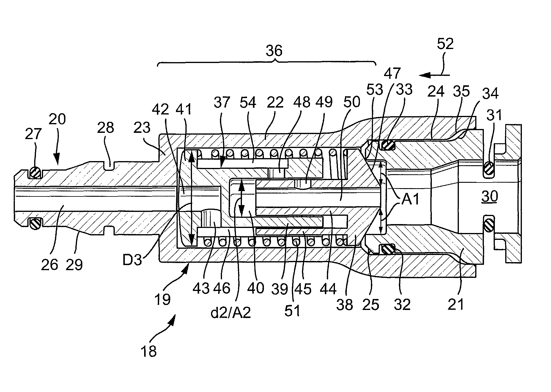
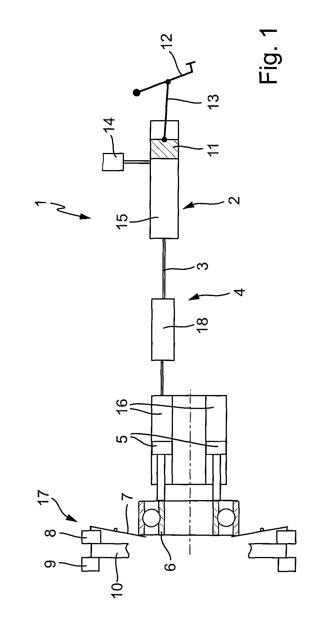
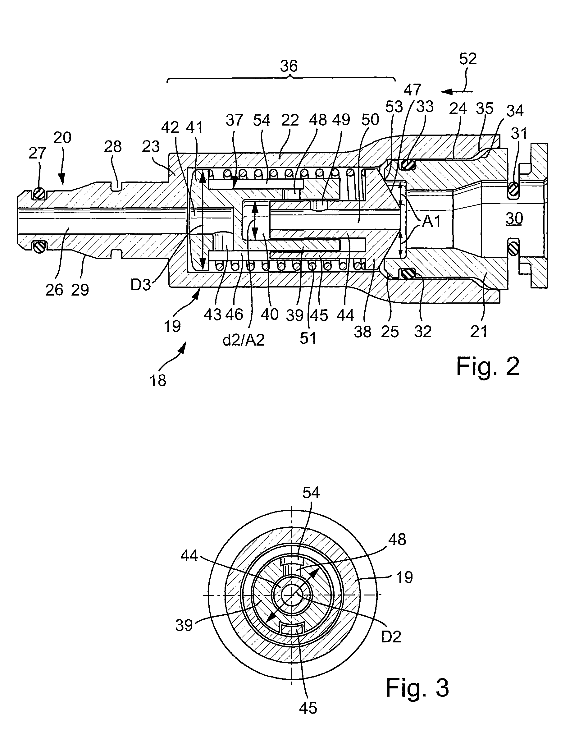
[0019]FIG. 1 shows as an example of a hydraulic power transmission system of a hydraulic clutch operation system 1 for a vehicle. The hydraulic clutch operation system 1 comprises a master cylinder 2 in a common manner that is connected hydraulically via a hydraulic pressure line 3 with a slave cylinder 4. The slave cylinder 4, for instance, can be formed as annular slave cylinder, a concentric slave cylinder, whereby an annular slave cylinder piston 5 is supported in annular cylinder housing. The annular slave cylinder 4 and the annular slave cylinder piston 5 again enclose an annular pressure chamber 16. Upon actuation of the slave cylinder piston 5, via a release bearing 6, a disk spring 7 is activated in a common manner. The disk spring 7 serves to activate a vehicle clutch 17. The latter comprises a pressure plate 8, a counter pressure plate 9 and a clutch disk 10. The disk spring 7 is preloaded such that it presses the pressure plate 8 onto a counter pressure plate 9 in the pr...


PUM


Abstract

A hydraulic element, in particular for arranging in a pressure line between a master cylinder and a slave cylinder of a hydraulic clutch actuating arrangement, having a housing which has a master-cylinder-side hydraulic connection and a slave-cylinder-side hydraulic connection and which holds a valve arrangement, a simpler design is obtained in that the valve arrangement has two valve bodies which are mounted in a floating fashion in the housing and which can be moved relative to one another counter to the force of a spring.

Description

[0001]This is a continuation of prior International Application PCT / DE2008 / 001438, filed Aug. 28, 2008, which claims priority to German Patent Application DE 10 2007 045 034.8, filed Sep. 20, 2007, the entire disclosures of which are hereby incorporated by reference herein.[0002]The present invention relates to a hydraulic element, in particular, for the arrangement in a pressure line between a master cylinder and a slave cylinder of a hydraulic clutch operation system, with housing that features a master-cylinder-side hydraulic connection and a slave-cylinder-side hydraulic connection and accommodates a valve arrangement.BACKGROUND[0003]From DE 100 59 382, FIG. 6, in particular, a generic hydraulic element, a so-called anti-vibration unit is disclosed, which comprises two independent spring-loaded check valves. The opening pressure in both flow directions can be determined individually by spring preload for each direction. Such a part consists of many components and is complicated ...

Claims


Application Information

Patent Timeline
Patent Type & Authority Patents(United States)
IPC IPC(8): F16D31/02
CPCF16D25/088F16D48/02F16D2048/0221F16D2048/0215F16D25/082F16D25/12F16D2300/22
Inventor RAMMHOFER, THOMASGRABENSTAETTER, JAN
Owner LUK VERMOGENSVERW MBH
Learn More