

Oil pump
a technology of oil pump and inner rotor, which is applied in the direction of liquid fuel engines, machines/engines, mechanical equipment, etc., can solve the problems of poor engagement between the outer teeth of the inner rotor and the inner teeth of the outer rotor, and achieve the effect of increasing the discharge amount of the oil pump without reducing the number of teeth
- Summary
- Abstract
- Description
- Claims
- Application Information
AI Technical Summary
Benefits of technology
Problems solved by technology
Method used
Image

Examples
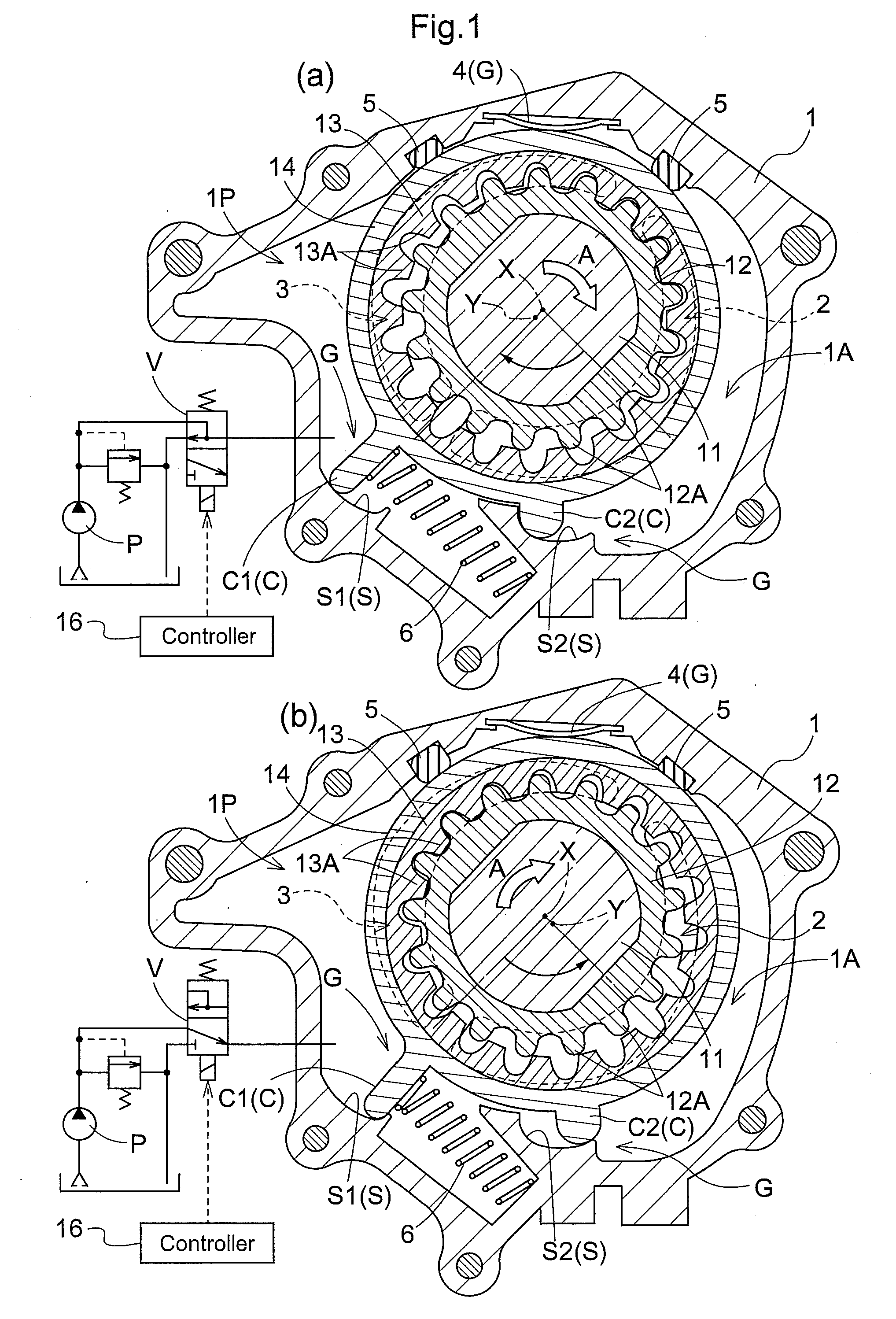
embodiment 1
Other Versions of Embodiment 1
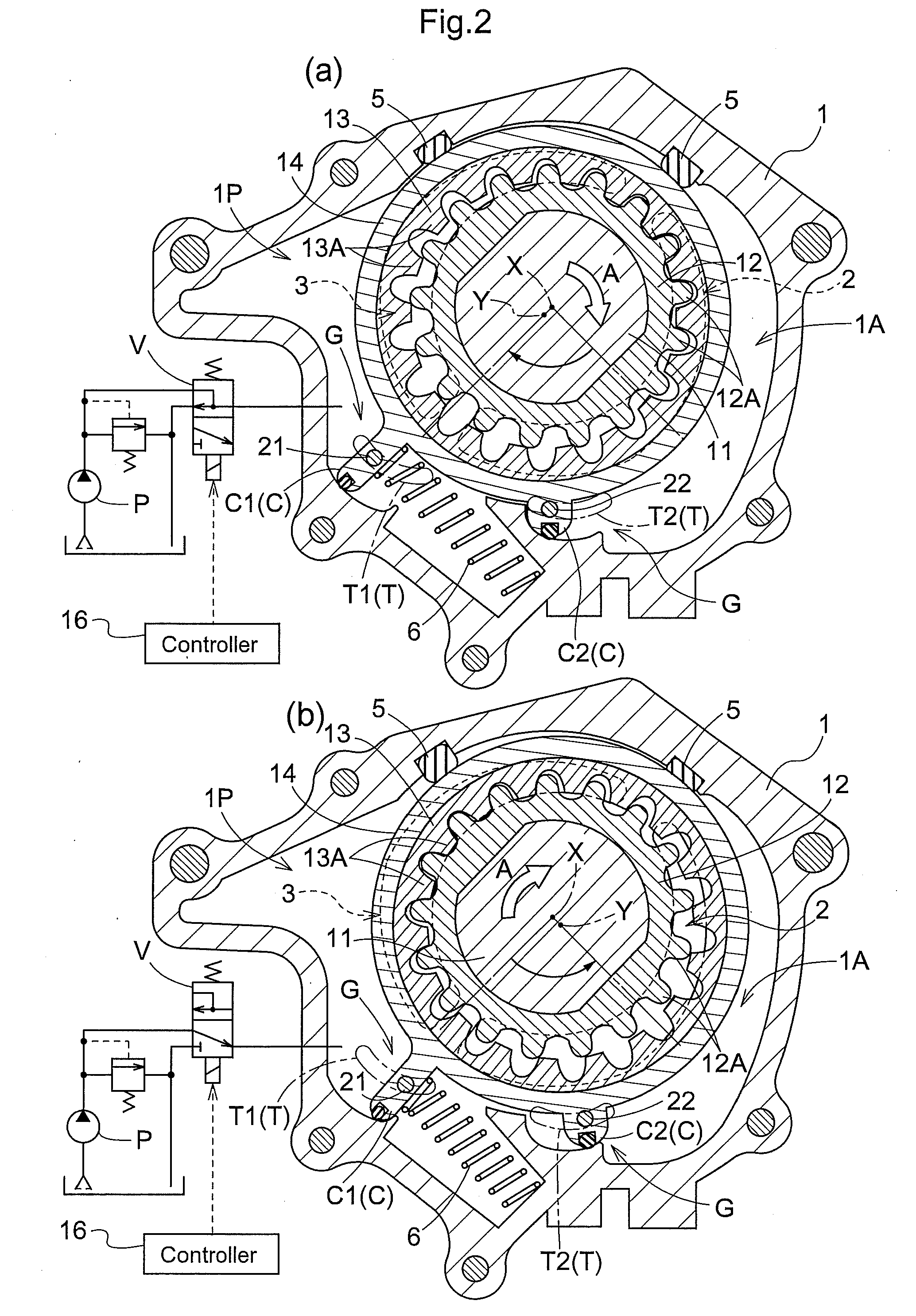
[0084]Instead of the above-described Embodiment 1, the present invention may be configured in the following manner (in the embodiment which will be describe below, the components having the same function as those in Embodiment 1 are designated with the same referential characters as in Embodiment 1).
[0085](a) As shown in FIG. 2, the guide means G includes: a first guide pin 21 and a second guide pin 22 which penetrate through the first arm portion C1 and the second arm portion C2 formed in the adjustment ring 14, respectively, in a direction parallel to the drive-rotation axis X; and an arc-shaped first guide groove T1 and an arc-shaped second guide groove T2 formed in the wall 1A of the casing 1 so as to correspond to the first guide pin 21 and the second guide pin 22, respectively.
[0086]The shapes of the first guide groove T1 and the second guide groove T2 are configured in such a manner that, when the adjustment ring 14 is moved, the driven axis Y is...
embodiment 2
Other Versions of Embodiment 2
[0117](a) In Embodiment 2, the guide means G is formed of the guide pin 31 and the guide groove 32. Alternatively, for example, the guide means G may be formed of: protrusions protruding from the outer periphery of the adjustment ring 14 in a direction orthogonal to the drive-rotation axis; and guide grooves formed in the casing 1 at positions opposing the respective protrusions. Specifically, this configuration is similar to that described in , but is different from Embodiment 1 in that the shapes of the two guide grooves are the same.
[0118](b) In addition, as the guide means G, protrusions may be formed in the casing 1, and guide grooves with which the respective protrusions come into contact may be formed in the adjustment ring 14. In this version, the shapes of the two guide grooves are the same.
embodiment 3
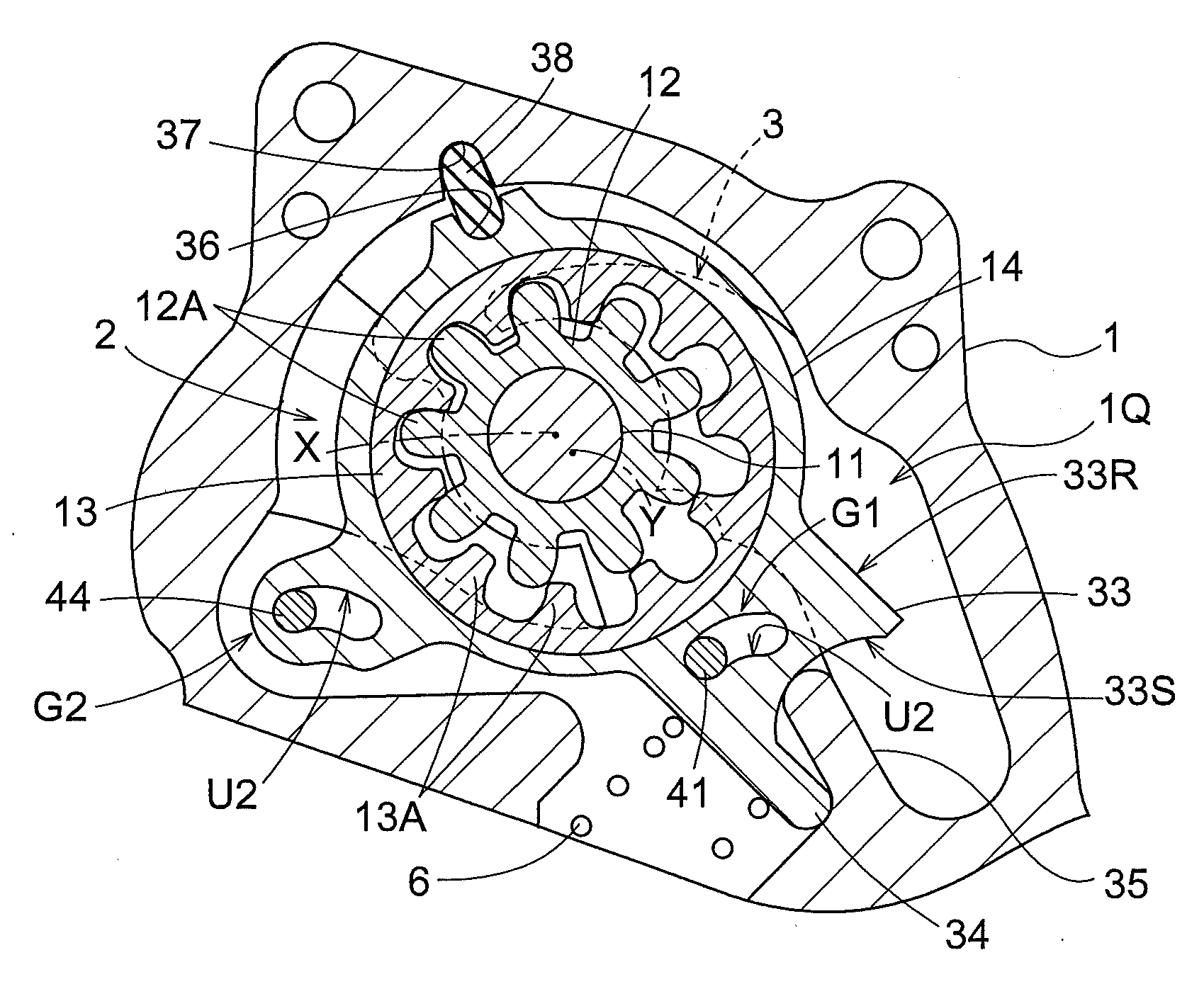
[0119]As shown in FIG. 8, the oil pump of Embodiment 3 is the same as the oil pump in Embodiment 1, in the configurations of the casing 1, the drive shaft 11, the inner rotor 12, and the outer rotor 13. Especially in Embodiment 3, the configuration for actuating the adjustment ring 14 is the same as that described in Embodiment 2, but the configuration of the guide means G is different. It should be noted that the components which are the same as those described in Embodiments 1 and 2 are designated with the same referential characters as in Embodiments 1 and 2.
[0120]Specifically, the guide means G is formed of a first guide portion G1 and a second guide portion G2. The first guide portion G1 is formed of: a first guide face U1 formed in a pocket portion 33V of the block portion 33; and a guide pin 41 which projects from the casing in a direction parallel to the drive-rotation axis X. The second guide portion G2 is formed of: a protrusion 42 which protrudes from the outer periphery ...
PUM
 Abstract
Description
Claims
Application Information