Oil pump including rotors that change eccentric positional relationship one-to another to adjust a discharge amount

a technology of eccentric position and oil pump, which is applied in the direction of liquid fuel engines, rotary piston liquid engines, machines/engines, etc., can solve the problems of poor engagement between the outer teeth of the inner rotor and the inner teeth of the outer rotor, and achieve the effect of increasing the discharge amount of the oil pump without reducing the number of teeth

Active Publication Date: 2015-09-08
AISIN SEIKI KK
View PDF21 Cites 3 Cited by
  • Summary
  • Abstract
  • Description
  • Claims
  • Application Information

AI Technical Summary

Benefits of technology

[0014]An object of the present invention is to provide a compact oil pump in which a discharge amount can be adjusted by changing an eccentric positional relationship between the inner rotor and the outer rotor.SOLUTION TO PROBLEM
[0044]With this configuration, by deforming a portion of the teeth profile outward of a circle having a radius satisfying Equation (1) to outside in a radial direction, or deforming a portion of the teeth profile inward of a circle having a radius satisfying Equations (2) and (3) to inside in the radial direction, or by the combination of these deformations, the discharge amount of the oil pump can be increased without reducing the teeth number.

Problems solved by technology

However, in the pump having the configuration described in Patent Document 1, though the biasing force of the spring is allowed to act, accuracy in the engagement between the outer teeth of the inner rotor and the inner teeth of the outer rotor is expected to become poor, since the cam ring is supported movable inward and outward and swingable in the direction of the center of the internal circle.

Method used


Image

  • Oil pump including rotors that change eccentric positional relationship one-to another to adjust a discharge amount
  • Oil pump including rotors that change eccentric positional relationship one-to another to adjust a discharge amount
  • Oil pump including rotors that change eccentric positional relationship one-to another to adjust a discharge amount

Examples


embodiment 1

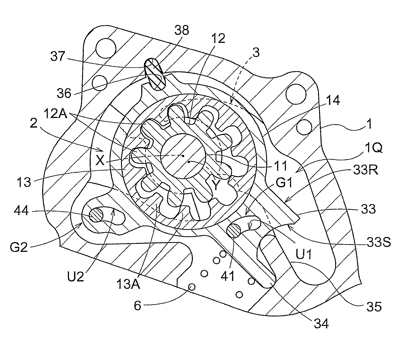
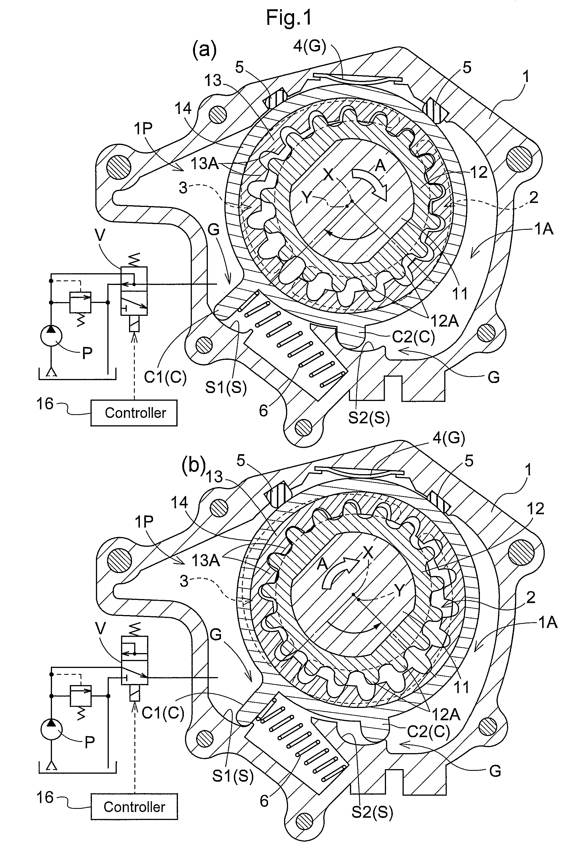
[0093]In this oil pump, like in the above-described Embodiment 1, the inner rotor 12 and the outer rotor 13 are disposed between two casings 1. In the wall of the casing 1, there are formed the suction inlet 2 and the discharge outlet 3. Inside the casing 1, a pressurization space 1Q is formed which is configured to allow a discharge pressure from the discharge outlet 3 to act on a block portion 33.

[0094]In each of two portions of the adjustment ring 14, a guide pin 31 is formed which projects in parallel with the drive-rotation axis X. The wall of the casing 1 is provided with guide grooves 32 into which respective protruding ends of the guide pins 31 are fitted. The guide means G is formed of these two guide pins 31 and two guide grooves 32. The function of the guide groove 32 will be described later.

[0095]In the outer periphery of the adjustment ring 14, the block portion 33 and an operation arm 34 (one example of operation portion) both protruding in a radial direction of the ad...

embodiment 2

[0103]Especially, it is possible to set the change characteristics of the discharge amount or discharge pressure of oil to those as shown in FIG. 5, with respect to the case where the rotations and revolutions of the outer rotor 13 are performed when the rotational speed of the drive shaft 11 is changed. It should be noted that, the mechanism alternately performing the rotation and the revolution as in FIG. 5 has a different shape from that of the guide groove 32 in

[0104]Referring to the same drawing, in the circumstance where the outer rotor 13 is rotated, the discharge amount or discharge pressure of oil is changed in direct proportion to the rotational speed of the inner rotor 12. Next, in the circumstance where the outer rotor is revolved, regardless of the changes in the rotational speed of the inner rotor 12, the discharge amount or discharge pressure of oil is not changed to a large extent. Especially, in the oil pump of Embodiment 2, as the pressure of the pressurization spa...

embodiment 3

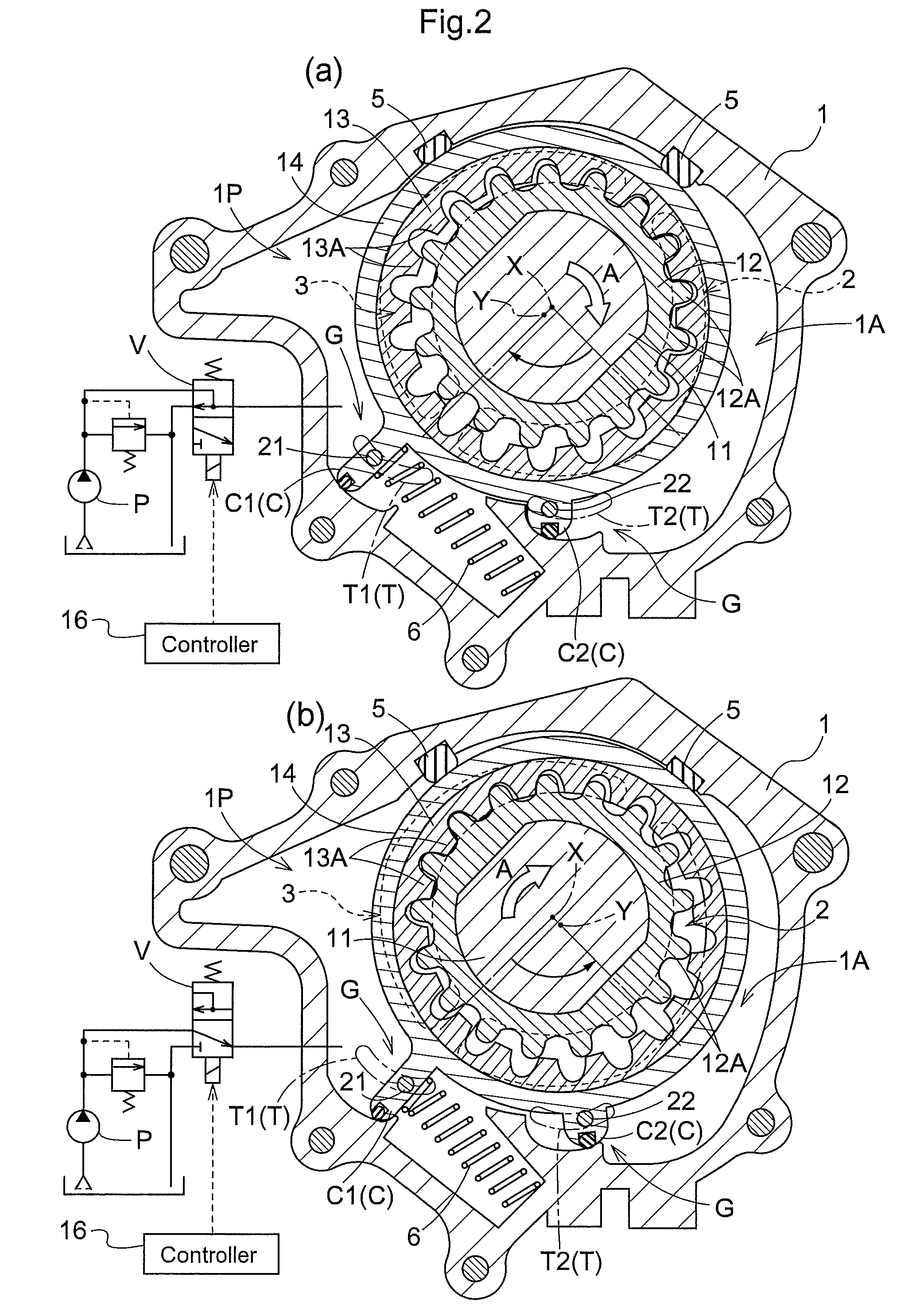
[0125 includes a configuration in which a rotational load is reduced, by discharging the oil in the cell R (a space between teeth profiles) formed between the inner rotor 12 and the outer rotor 13, and thus releasing the pressure of the oil trapped in the cell R.

[0126]In this type of the oil pump, there happens a phenomenon that oil is trapped in the cell R which is the intermediate region in the outer teeth 12A of the inner rotor 12 and the inner teeth 13A of the outer rotor 13 between the suction inlet 2 and the discharge outlet 3 positioned on the opposite side of the region in which the outer teeth 12A and the inner teeth 13A are engaged most deeply.

[0127]Specifically, as shown in FIG. 12, in the intermediate region, a pair of adjacent teeth from among the outer teeth 12A of the inner rotor 12 and a corresponding pair of adjacent teeth from among the inner teeth 13A of the outer rotor 13 are brought into contact, and a state is reached in which the oil is trapped in the cell R a...


PUM


Abstract

An oil pump includes: an inner rotor rotatable with a drive shaft in a unified manner on a drive-rotation axis; an outer rotor which has inner teeth configured to engage with outer teeth of the inner rotor and is rotatable about a driven axis eccentric to the drive-rotation axis; and an adjustment ring for rotatably supporting the outer rotor. A guide means which allows the adjustment ring to rotate about the driven axis, while allowing the driven axis to revolve about the drive-rotation axis, is formed of: first and second arm portions provided on the adjustment ring; and first and second guide faces with which the first and second arm portions are brought into slidable contact.

Description

TECHNICAL FIELD[0001]The present invention relates to an oil pump, and particularly to an oil pump having a structure in which an outer rotor having inner teeth and an inner rotor having outer teeth are engaged with each other in an eccentric state, which pump is configured to adjust a discharge amount by changing an eccentric positional relationship.BACKGROUND ART[0002]As the oil pump having the configuration described above, Patent Document 1 discloses an oil pump having an inner rotor 3 configured to be driven-rotated, and an outer rotor 4 which is configured to engage with outer teeth of the inner rotor 3 and disposed at an eccentric position to the inner rotor 3. The outer rotor 4 is rotatably supported on an inner periphery of a cam ring 5, and the cam ring 5 is supported by a support pin 10 swingably in a radial direction and at the same time movably in a direction to a center of an internal circle. A biasing force of a spring 7 is allowed to act on the cam ring 5 so that a v...

Claims


Application Information

Patent Timeline
Patent Type & Authority Patents(United States)
IPC IPC(8): F04C2/10F04C14/22F04C14/08F04C2/08
CPCF04C2/102F04C2/086F04C14/226F04C14/08
Inventor ONO, HISASHIHAMASAKI, MASAHARUNISHIDA, YUKINUNAMI, KOJIKAZAOKA, SHINJI
Owner AISIN SEIKI KK
Why Eureka
Try Eureka