Crank case ventilation filter assembly; and methods

a ventilation filter and crank case technology, applied in mechanical equipment, machines/engines, separation processes, etc., can solve the problem of carrying substantial amounts of fine particulate contaminants

Active Publication Date: 2011-01-27
DONALDSON CO INC +1
View PDF14 Cites 58 Cited by
  • Summary
  • Abstract
  • Description
  • Claims
  • Application Information

AI Technical Summary

Benefits of technology

[0011]It is noted that there is no requirement that an assembly or component include all of

Problems solved by technology

In addition, such gas streams also carry substantial amounts

Method used


Image

  • Crank case ventilation filter assembly; and methods
  • Crank case ventilation filter assembly; and methods
  • Crank case ventilation filter assembly; and methods

Examples


Embodiment Construction

I. Crankcase Ventilation (CCV) Filter Assembly Features

A. General Features of the Assembly

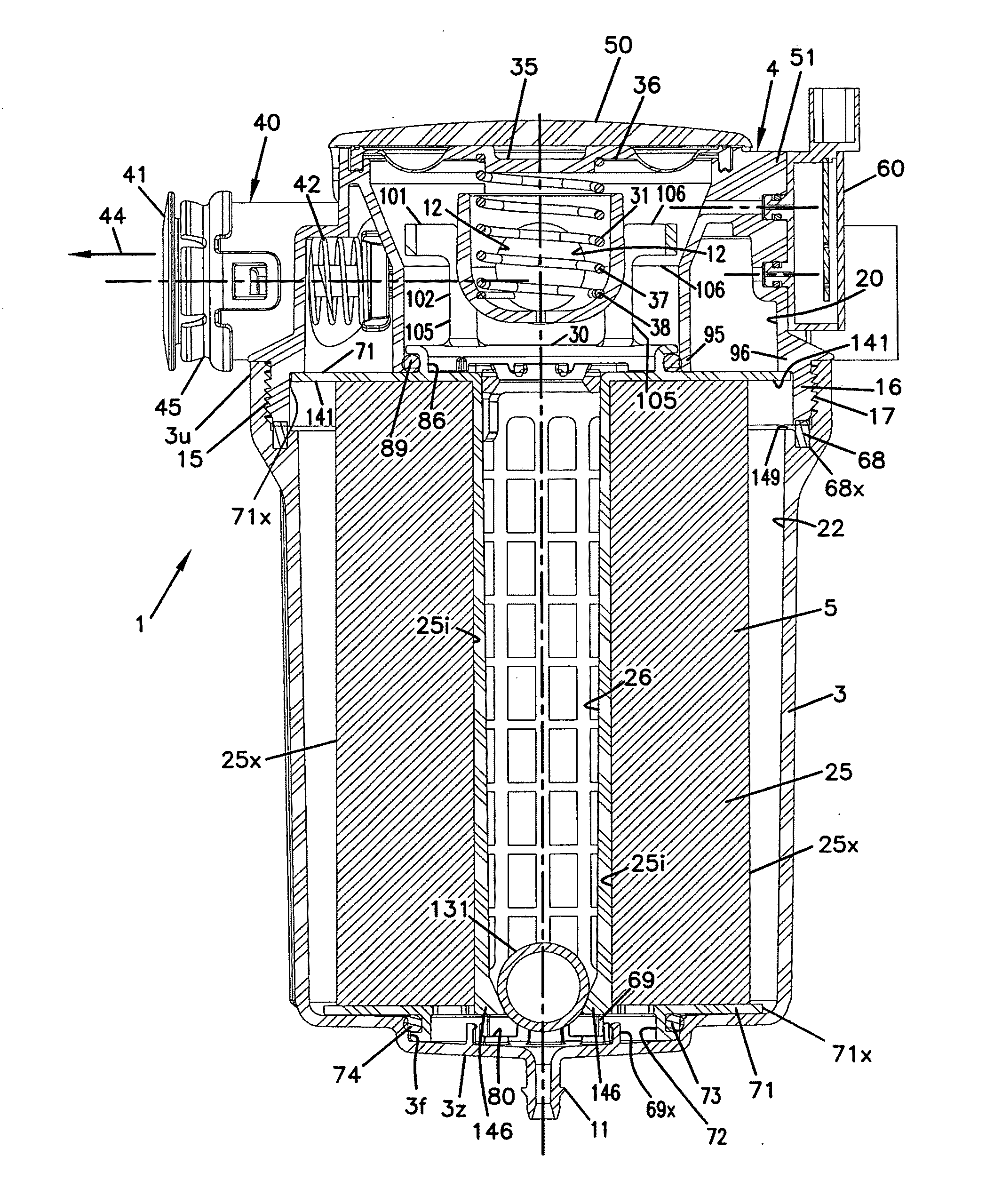
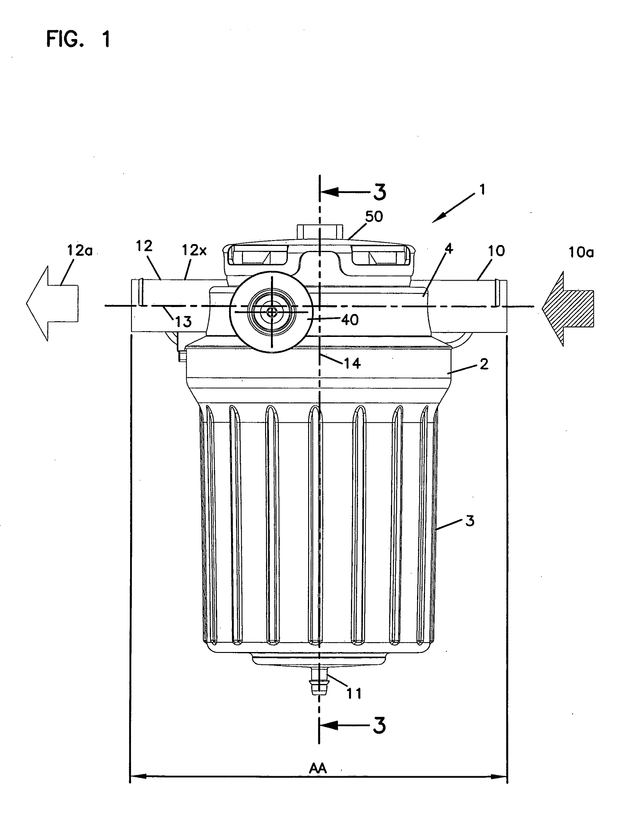
[0043]The reference numeral 1, FIG. 1, generally represents a crankcase ventilation filter assembly according to the present disclosure. The assembly 1, depicted in FIG. 1, includes a housing 2 defining a housing interior and including a housing base 3, a top cover or cover assembly 4 and an internally received, serviceable, i.e. removable and replaceable, filter cartridge service component, not depicted in FIG. 1 but shown in FIG. 5 at reference numeral 5.

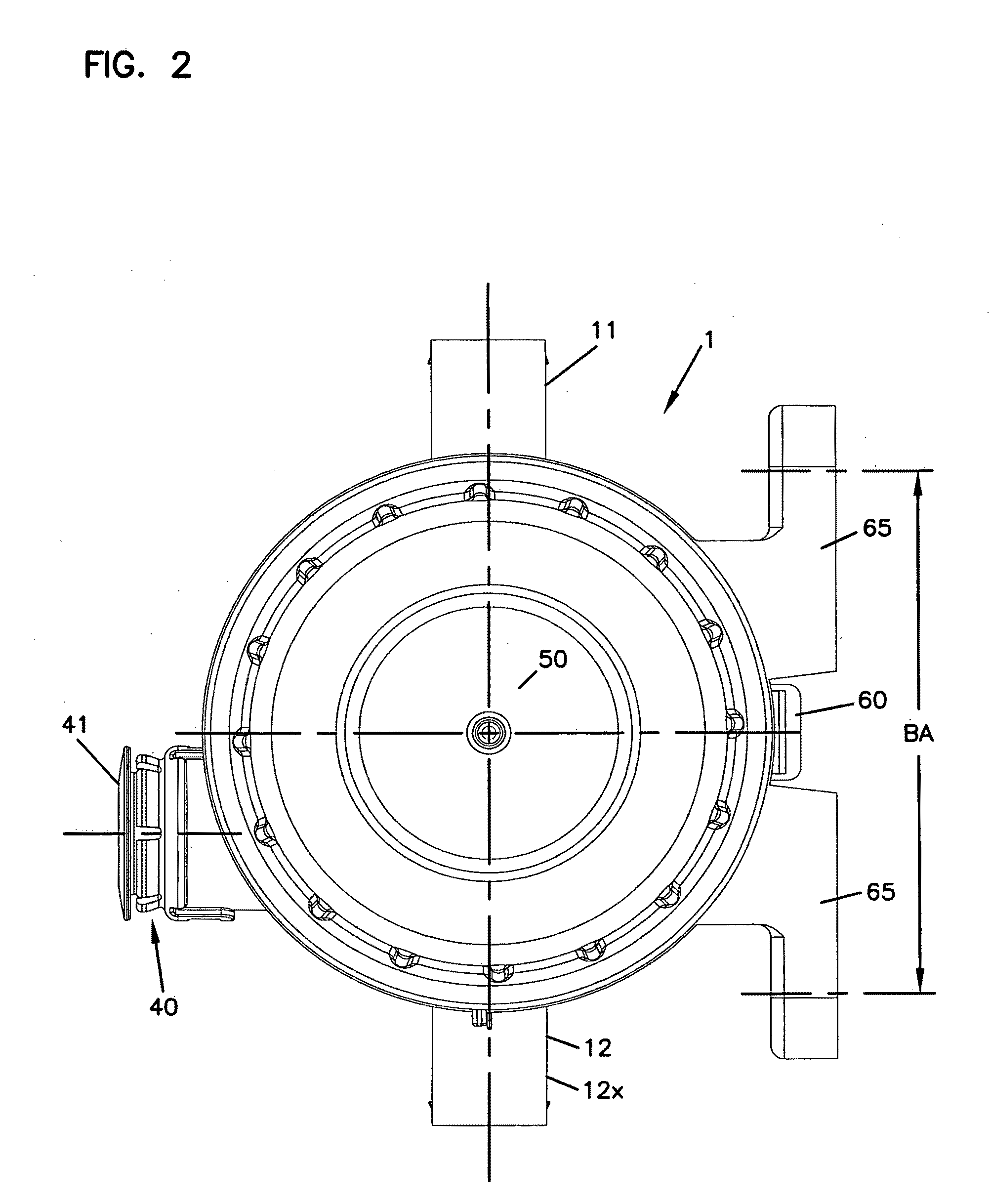
[0044]In general, the housing 2 includes a gas flow inlet tube 10, a liquid drain outlet 11, and a gas flow outlet tube 12. For the example assembly 1 depicted in FIG. 1, the gas flow inlet tube 10 and the gas flow outlet tube 12 are positioned in the cover assembly 4; and, liquid drain outlet 11 is positioned in the housing base 3.

[0045]Referring to FIG. 1, it is noted for the example system, the gas flow inlet tube 10 and the gas flow outle...


PUM

PropertyMeasurementUnit
Fractionaaaaaaaaaa
Angleaaaaaaaaaa
Angleaaaaaaaaaa

Abstract

Crankcase ventilation filter arrangements and components therefore are described. Example arrangements are described. In one, a serviceable filter cartridge includes a check valve therein, for protection during vehicle rollover. Handle arrangements are also described. Methods of use are described.

Description

CROSS-REFERENCE TO RELATED APPLICATION[0001]This application is being filed on 31 Jul. 2008, as a PCT International Patent application in the name of Donaldson Company, Inc., a U.S. national corporation, applicant for the designation of all countries except the US, and Gregoire Jacob and Robert Wood, both citizens of Belgium, applicants for the designation of the US only, and claims priority to U.S. Provisional patent application Ser. No. 60 / 962,993, filed Aug. 2, 2007.[0002]The above referenced application, includes, with edits, the disclosure of U.S. provisional application 60 / 962,993, filed Aug. 2, 2007. The complete disclosure of U.S. 60 / 962,993 is incorporated herein by reference. A claim of priority to 60 / 962,993 is made, to the extent appropriate.FIELD OF DISCLOSURE [0003]This disclosure relates to systems and methods for separating hydrophobic fluids (such as oils) which are entrained as aerosols, from gas streams (for example air streams). Further, the arrangements also pro...

Claims


Application Information

Patent Timeline
IPC IPC(8): F01M13/00
CPCB01D46/0031B01D46/0087F01M2013/0438F01M13/04B01D46/2414B01D2279/30
Inventor JACOB, GREGORIE
Owner DONALDSON CO INC
Why Eureka
Try Eureka