Thermal print head, thermal printer and printer system

a printing head and printer technology, applied in printing and other directions, can solve the problems of data deficiency, long printing time, and disturb the normal transfer of signals between each other,

Inactive Publication Date: 2011-01-27
ROHM CO LTD
View PDF1 Cites 16 Cited by
  • Summary
  • Abstract
  • Description
  • Claims
  • Application Information

AI Technical Summary

Benefits of technology

[0033]A second aspect of the present invention provides a thermal printer with a wireless communication function. This thermal printer comprises the thermal print head according to the first aspect of the present invention, so that both printing on the print target and data transmission / reception to and from the print target can be executed.

Problems solved by technology

This leads to the drawback that the printing takes a long time.
However, an excessively high transfer rate may provoke deformation of the waveform of the signals on respective signal lines between the control unit 995 of the thermal printer 990 and the thermal print head 999, resulting in data deficiency.
Besides, radiation may take place in the respective signal lines, which may disturb normal transfer of the signals between each other.
Accordingly, a limitation is inevitably imposed on the transfer rate of the image data between the control unit 995 of the thermal printer 990 and the thermal print head 999, and hence it is difficult to transfer the image data at a higher speed.
Especially in the case of printing the image data containing an enormous data amount, the printing speed of the thermal print head 999 is subjected to such limitation.
Therefore, the line length is also limited.
Especially in the case where the antenna is located distant from the RFID tag, the print target, the reliability of the data transmission / reception may be degraded.

Method used


Image

  • Thermal print head, thermal printer and printer system
  • Thermal print head, thermal printer and printer system
  • Thermal print head, thermal printer and printer system

Examples


first embodiment

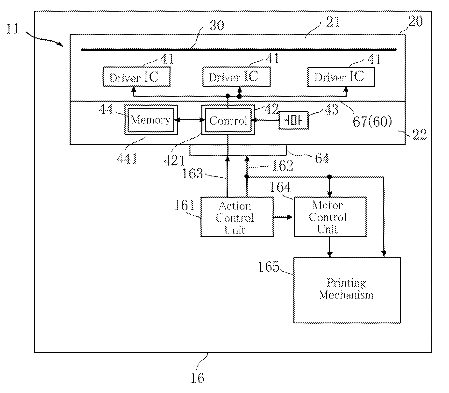
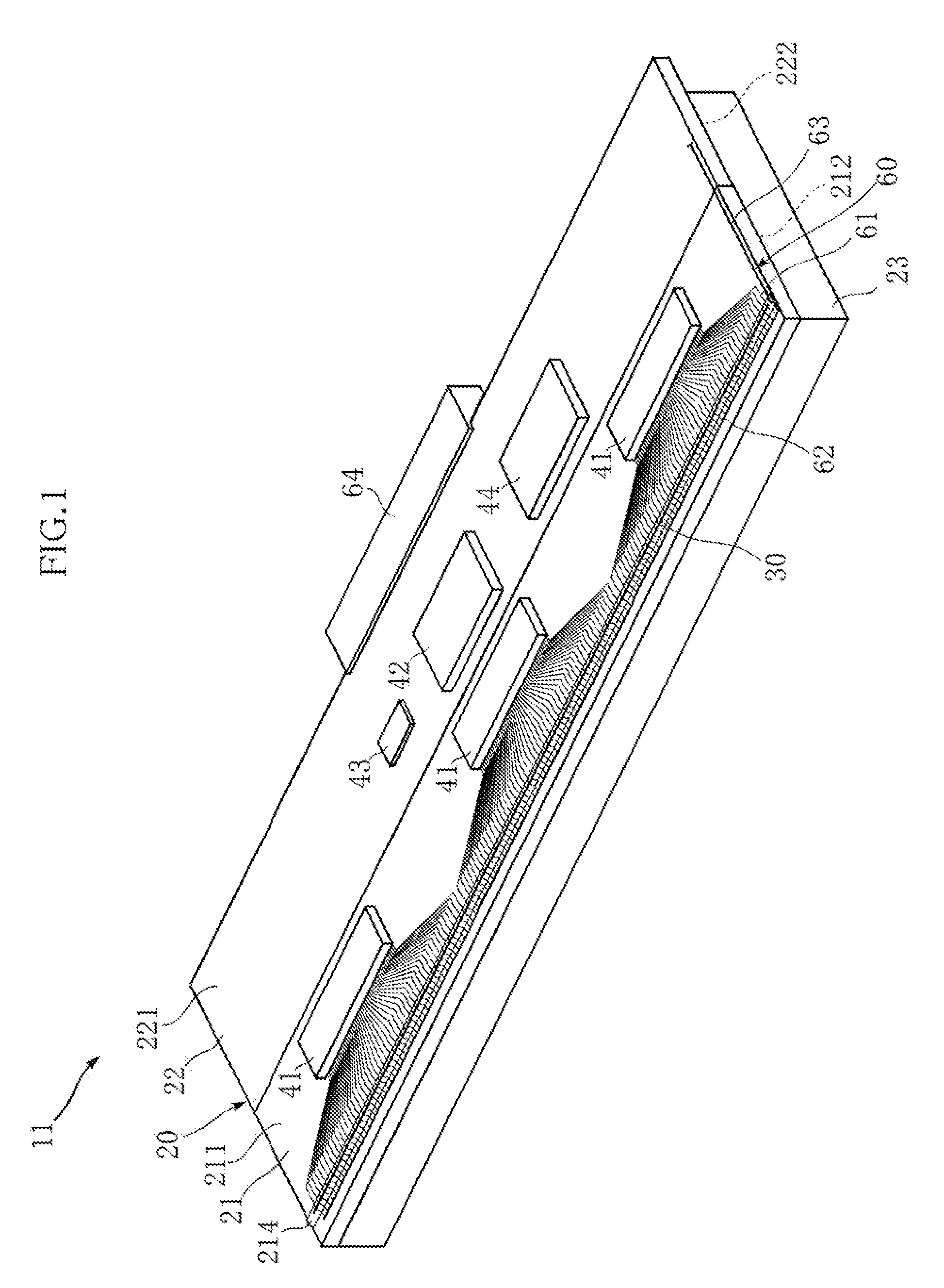
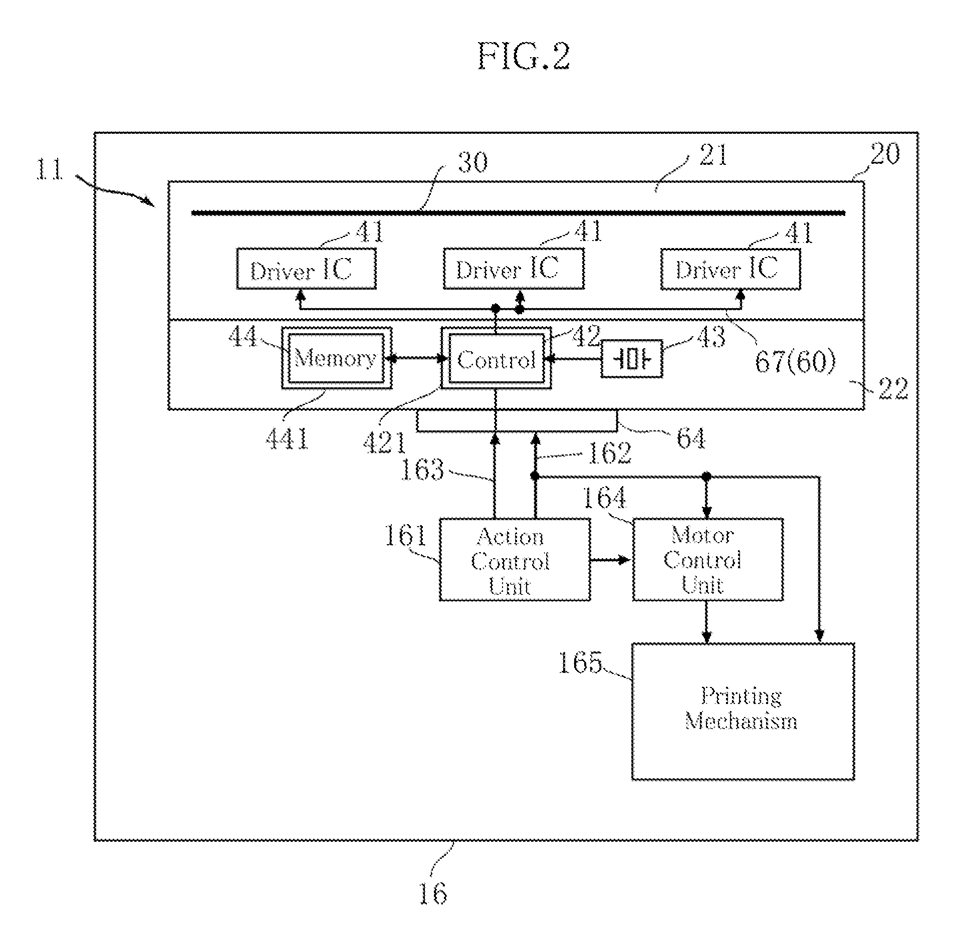
[0053]FIG. 1 depicts a thermal print head according to the present invention, and FIG. 2 is a block diagram of a thermal printer including the thermal print head. The thermal print head 11 and the thermal printer 16 are configured to print letters and images on recording paper such as thermosensitive paper or other kinds of recording medium (“print target”). The thermal print head 11 according to this embodiment includes a substrate 20, a heat dissipater 23, a heating resistor 30, a driver IC 41, a control chip 42, a quartz oscillator 43, a memory chip 44 and a connector 64.

[0054]The substrate 20 serves as the case of the thermal print head 11, and is constituted of a heating function unit 21 and a circuit board 22 in this embodiment. Unlike this embodiment, the substrate 20 may be constituted of a single material.

[0055]The heating function unit 21 is made of an insulating material such as a ceramic, and formed in a rectangular shape, for example. On a front face 211 of the heating ...

second embodiment

[0095]FIG. 10 is a block diagram of a printer system constituted of a plurality of thermal printers each including a thermal print head according to the present invention. In the printer system 18, the plurality of thermal printers 17 is connected to the control unit 182 through the I2C signal line 163, so as to make data communication.

[0096]To be more detailed, the printer system 18 includes, as shown in FIG. 10, a control unit 182 connected to a personal computer 181 for example, and the plurality of thermal printers 17 connected to the control unit 182 in a bus configuration through the I2C signal line 163. In the printer system 18, for example the control unit 182 may serve as the master device, and the plurality of thermal printers 17 as the slave device.

[0097]The control unit 182 includes for example a microcomputer, and integrally controls the printing action of the thermal printers 17 connected thereto through the I2C signal line 163. The control unit 182 includes an integra...

third embodiment

[0104]FIGS. 12 and 13 illustrate a thermal print head according to the present invention. The thermal print head 13 according to this embodiment is different from that of the foregoing embodiments in including a coil antenna 51, a magnetic sheet 52, a driver IC 45, a connector 65, and a cover 80. The thermal print head 13 can be incorporated for example in a Radio Frequency IDentification (RFID) tag printer through the connector 64, 65 as will be subsequently described, for executing the printing on an RFID tag sheet 70, corresponding to the recording paper 70, and data transmission / reception to and from the RFID tag sheet 70. Here, an encapsulating resin 49 shown in FIG. 13 is omitted in FIG. 12.

[0105]The RFID tag sheet, an example of the recording paper 70 for the thermal print head 13 will hereunder be described. The recording paper 70 is constituted as the RFID tag sheet, including for example a base paper 74 and a plurality of RFID tags 75 arranged thereon. The RFID tags 75 eac...


PUM


Abstract

A thermal print head includes a heating resistor for forming images on a print target by generating heat, and a driver for controlling power supply to the heating resistor. The thermal print head also includes a storage unit and a controller. The storage unit stores print data inputted from outside. The controller causes a transfer action and a printing action to be repeated alternately, wherein the transfer action includes retrieving print data from the storage unit and transferring the retrieved print data to the driver, and the printing action includes causing the driver to retain the transferred print data and supplying power to portions of the heating resistor selected in accordance with the print data retained by the driver, so as to conduct printing.

Description

BACKGROUND OF THE INVENTION[0001]1. Field of the Invention[0002]The present invention relates to a thermal print head, a thermal printer including the thermal print head, and a printer system including a plurality of thermal printers.[0003]2. Related Art[0004]There has been known a thermal print head or a thermal printer incorporating a thermal print head (see JP-A-No. 2005-186302, for example) that causes the heating resistor to selectively heat recording paper (such as thermosensitive paper) or thermal transfer ink ribbon, so that letters or images are to be printed.[0005]FIG. 16 is a block diagram of an example of the thermal printer including the conventional thermal print head. The thermal printer 990 shown therein includes the thermal print head 999. The thermal print head 999 includes a substrate 991, a heating resistor 992, a driver IC 993, and a connector 994. On the substrate 991, an elongated heating resistor 992 is provided. The thermal print head 999 is connected to a c...

Claims


Application Information

Patent Timeline
Patent Type & Authority Applications(United States)
IPC IPC(8): B41J2/32
CPCB41J2/355
Inventor MURAKI, KAORUNAKANISHI, MASATOSHI
Owner ROHM CO LTD
Why Eureka
Try Eureka