Compound-eye imaging apparatus

Inactive Publication Date: 2011-01-27
FUJIFILM CORP
View PDF7 Cites 106 Cited by
  • Summary
  • Abstract
  • Description
  • Claims
  • Application Information

AI Technical Summary

Benefits of technology

[0035]According to the compound-eye imaging apparatus according to the thirteenth aspect, if the automatic storage of all the plurality of plane images has been selected, the plurality of p

Problems solved by technology

However, since the image which is actually displayed on the display unit is the image before being enlarged, there is a problem in that the user cannot confirm details of the image.
Moreover, in the invention described in Japanese Patent Application Laid-Open No. 5-148090, only one imaging element is provided, and thus, there is a problem in that only the enlarged image can be recorded.
In the first mode of the invention described in Japanese Patent Application Laid-Open No. 2

Method used


Image

  • Compound-eye imaging apparatus
  • Compound-eye imaging apparatus
  • Compound-eye imaging apparatus

Examples


first embodiment

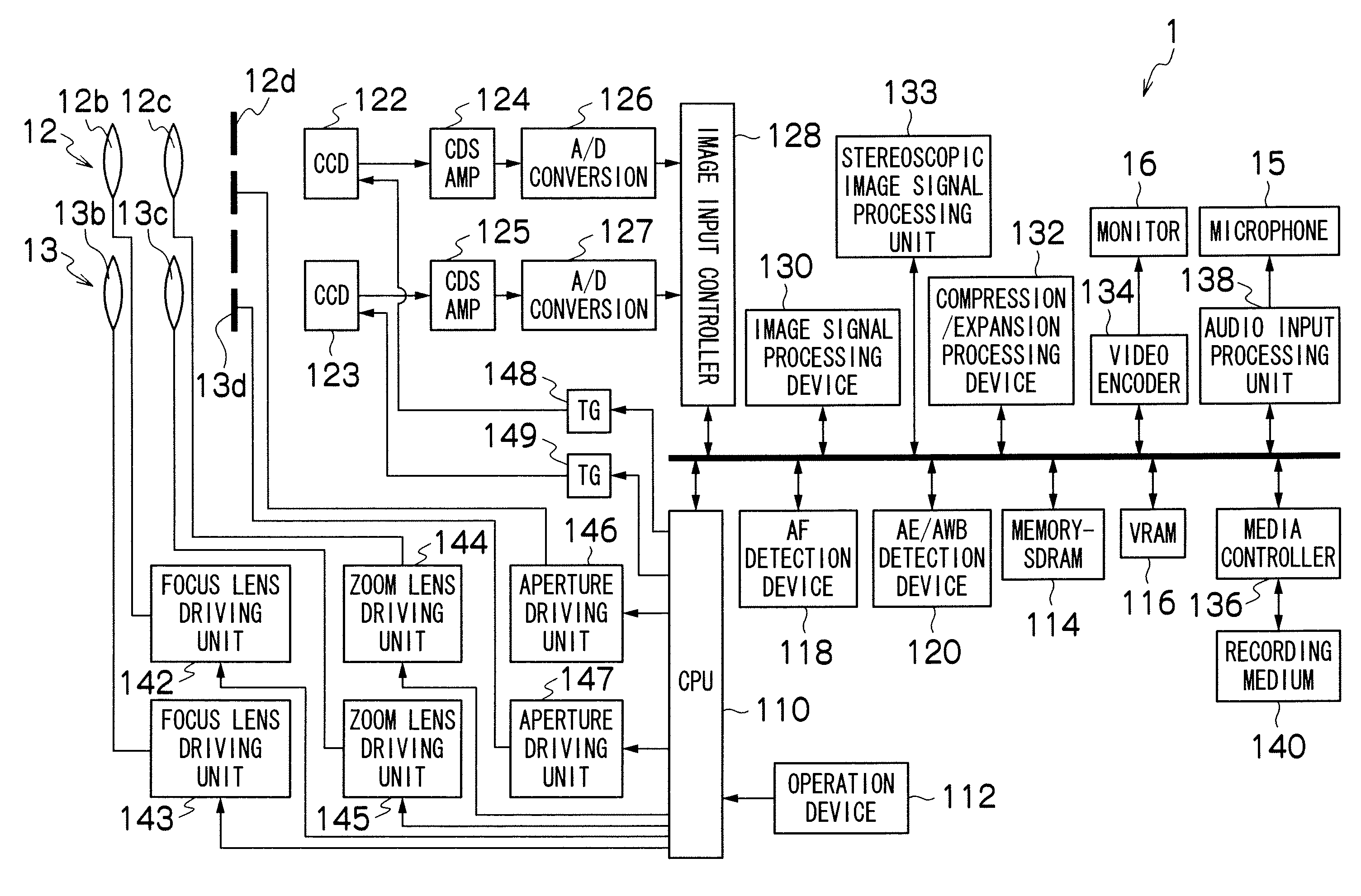
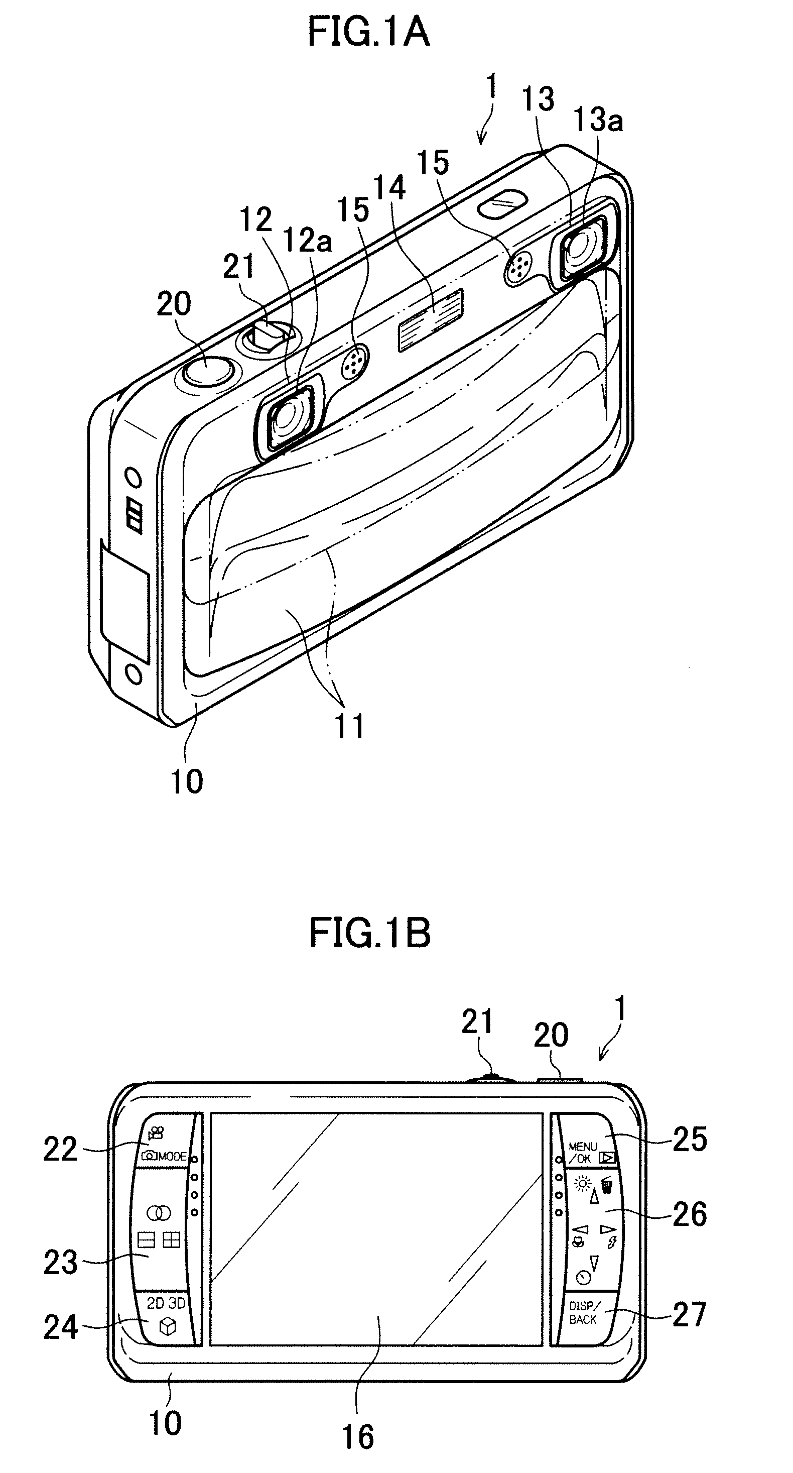
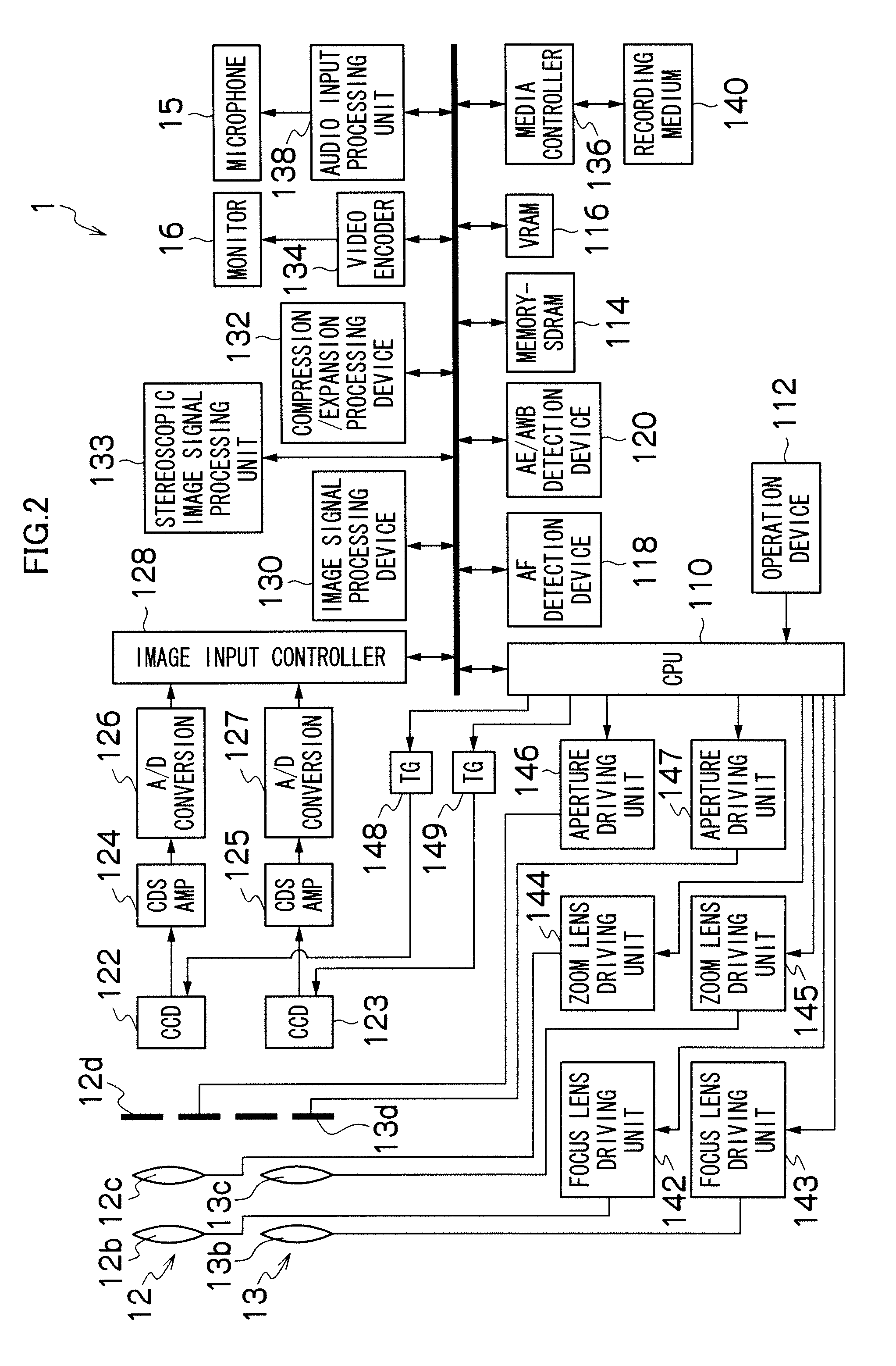
[0058]FIGS. 1A and 1B are schematic diagrams of a compound-eye digital camera 1 which is the compound-eye imaging apparatus according to the present invention, and FIG. 1A is a front view and FIG. 1B is a rear view. The compound-eye digital camera 1 is the compound-eye digital camera 1 including a plurality (two are illustrated in FIG. 1) of imaging systems, and can take a stereoscopic image of the same subject viewed from a plurality of viewpoints (two viewpoints of left and right are illustrated in FIG. 1), and a single viewpoint image (two-dimensional image). Moreover, the compound-eye digital camera 1 can also record and reproduce moving images and audio, in addition to still images.

[0059]A camera body 10 of the compound-eye digital camera 1 is formed in a generally rectangular parallelepiped box shape, and on the front face thereof, as shown in FIG. 1A, a barrier 11, a right imaging system 12, a left imaging system 13, a flash 14 and a microphone 15 are mainly provided. Moreove...

second embodiment

[0164]In the first embodiment of the present invention, when the simultaneous tele / wide image taking mode has been set, the zoom positions of the right imaging system 12 and the left imaging system 13 are decided, and then the monitor 16 is set to the 2D mode. However, the order thereof is not limited thereto.

[0165]A second embodiment of the present invention is a mode in which when the simultaneous tele / wide image taking mode has been set, the monitor 16 is set to the 2D mode, and then the zoom positions of the right imaging system 12 and the left imaging system 13 are decided. A compound-eye digital camera 2 of the second embodiment is different from the compound-eye digital camera 1 of the first embodiment, only in the image taking process in the simultaneous tele / wide image taking mode, and thus, only the image taking process in the simultaneous tele / wide image taking mode will be described, and descriptions of other portions are omitted. Moreover, the same portions as those of ...

third embodiment

[0174]In the first embodiment of the present invention, at the time of the transition from the simultaneous tele / wide image taking mode to the 3D image taking mode, the zoom positions of the right imaging system 12 and the left imaging system 13 are decided, and then the monitor 16 is set to the 3D mode. However, the order thereof is not limited thereto.

[0175]A third embodiment of the present invention is a mode in which, at the time of the transition from the simultaneous tele / wide image taking mode to the 3D image taking mode, the monitor 16 is set to the 3D mode, and then the zoom positions of the right imaging system 12 and the left imaging system 13 are decided. A compound-eye digital camera 3 of the third embodiment is different from the compound-eye digital camera 1 of the first embodiment, only in a process of the transition from the simultaneous tele / wide image taking mode to the 3D image taking mode, and thus, only the process of the transition from the simultaneous tele / w...


PUM


Abstract

An object is to provide a compound-eye imaging apparatus in which a plurality of plane images in different image taking ranges can be taken by a plurality of image pickup devices, and also, a user can recognize the image taking ranges of the plurality of plane images and confirm details of a subject. When a simultaneous tele/wide image taking mode is set, zoom positions of a zoom lens of a right imaging system and a zoom lens of a left imaging system are set to be different from each other, and a wide-side image can be taken by the right imaging system, and a tele-side image can be taken by the left imaging system. Based on the positions of the zoom lens and the zoom lens, guidance, which is a figure in which a frame indicating the image taking range of a wide-image and a frame indicating the image taking range of a tele-image are superimposed so that centers of the frame and the frame coincide with each other, is generated, and a live view image taken by the right imaging system and the guidance are displayed in a superimposed manner. The guidance is displayed so as to be superimposed on a tele-side live view image.

Description

BACKGROUND OF THE INVENTION[0001]1. Field of the Invention[0002]The present invention relates to a compound-eye imaging apparatus, and more particularly, to a compound-eye imaging apparatus which can take a plurality of plane images in different image taking ranges.[0003]2. Description of the Related Art[0004]Japanese Patent Application Laid-Open No. 5-148090 proposes, in a camera in which optical zoom of up to 3× is enabled, a video camera in which, if an instruction for the zoom of 3× or more has been inputted, an image taken with the 3× optical zoom is displayed on a display unit, and a range to be enlarged by electronic zoom is surrounded by a frame.[0005]Japanese Patent Application Laid-Open No. 2004-207774 proposes a digital camera in which subject images are formed on two imaging elements of different sizes, an image taken by a larger imaging element (wide-imaging element) is displayed on a display unit, and also, a range to be taken by a smaller imaging element (tele-imaging...

Claims


Application Information

Patent Timeline
IPC IPC(8): H04N13/02H04N13/239
CPCH04N5/2251H04N5/232H04N5/23212H04N5/23293H04N13/0456H04N13/0239H04N13/0289H04N13/0296H04N13/0409H04N5/23296H04N13/289H04N13/31H04N13/296H04N13/239H04N13/361H04N23/673H04N23/631H04N23/635H04N23/69H04N23/843H04N25/134
Inventor WAKABAYASHI, SATORU
Owner FUJIFILM CORP
Why Eureka
Try Eureka