
Handover controlling method, radio base station, and mobile station

a control method and control method technology, applied in the direction of wireless communication services, electrical equipment, wireless commuication services, etc., can solve the problems of reducing radio transmission efficiency and wasting radio resources, and achieve the effect of avoiding redundant transmission and improving transmission efficiency

Active Publication Date: 2011-01-27
NTT DOCOMO INC
View PDF9 Cites 6 Cited by
  • Summary
  • Abstract
  • Description
  • Claims
  • Application Information

AI Technical Summary

Benefits of technology

[0023]Accordingly, the present invention has been made in view of the above-described problem. An object of the present invention is to provide a handover controlling method, a radio base station and a mobile station which are capable of improving transmission efficiency by notifying a mobile station only of difference information between information set by a connection source radio base station and information set by a connection target radio base station at the time of a handover between the radio base stations and thus avoiding transmitting redundant information.
[0033]As described above, the present invention can provide a handover controlling method, a radio base station and a mobile station which are capable of improving transmission efficiency by notifying a mobile station only of difference information between information set by a connection source radio base station and information set by a connection target radio base station at the time of a handover between the radio base stations and thus avoiding transmitting redundant information.

Problems solved by technology

However, the above-described mobile communication system has a problem of a waste of radio resources and a reduction in radio transmission efficiency.

Method used


Image

  • Handover controlling method, radio base station, and mobile station
  • Handover controlling method, radio base station, and mobile station
  • Handover controlling method, radio base station, and mobile station

Examples


Embodiment Construction

(Configuration of Mobile Communication System According to First Embodiment of the Present Invention)

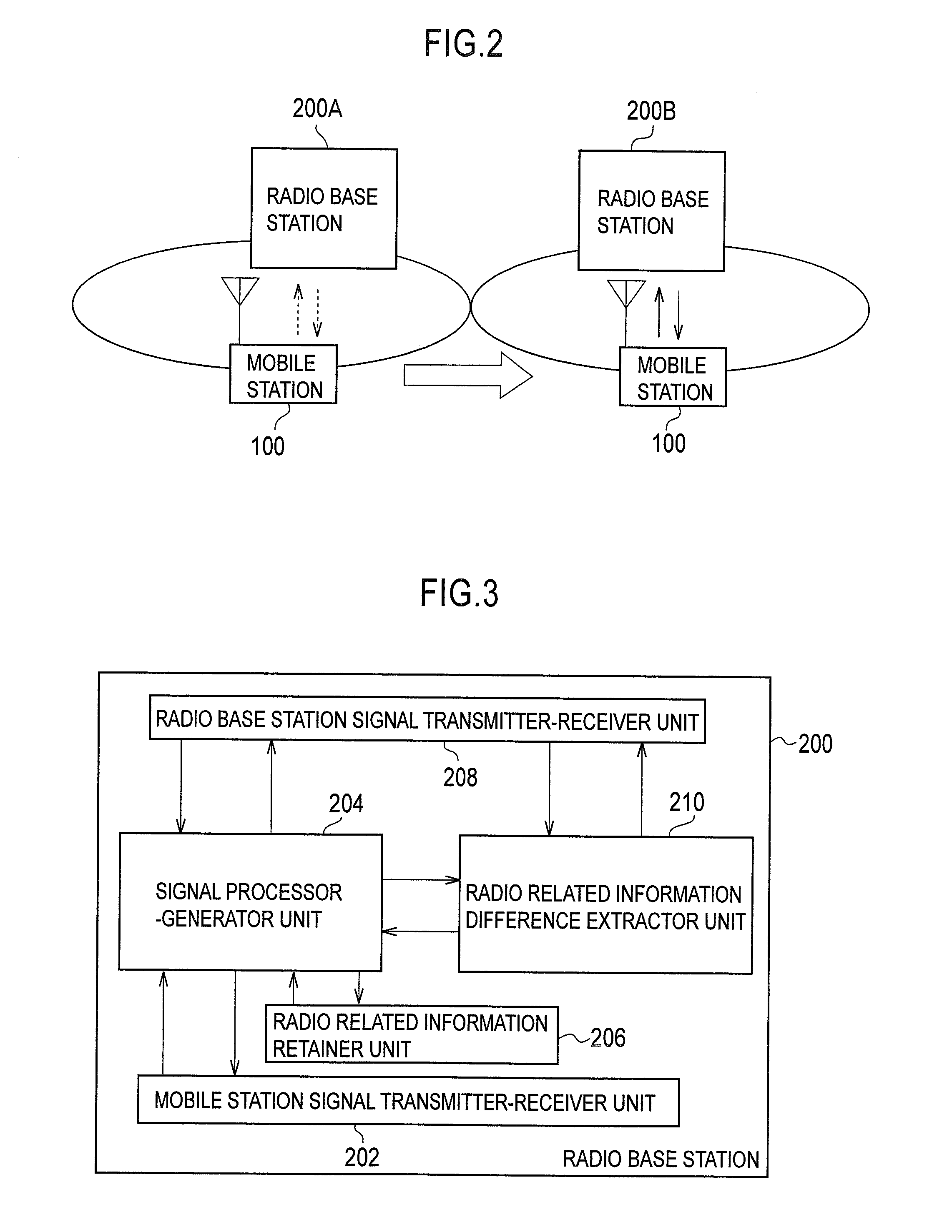
[0041]A configuration of a mobile communication system according to a first embodiment of the present invention will be described with reference to FIG. 2 to FIG. 7. In this embodiment, a mobile communication system of the LTE scheme will be described as an example of a mobile communication system. However, the present invention is also applicable to mobile communication systems other than the mobile communication system of the LTE scheme.

[0042]The configuration of the mobile communication system according to the first embodiment of the present invention will be described with reference to FIG. 2. It is to be noted that constituents having the same function are designated by the same reference numerals throughout the drawings for describing this embodiment and repetitive explanations will be omitted.

[0043]As shown in FIG. 2, the mobile communication system according to this embodimen...


PUM


Abstract

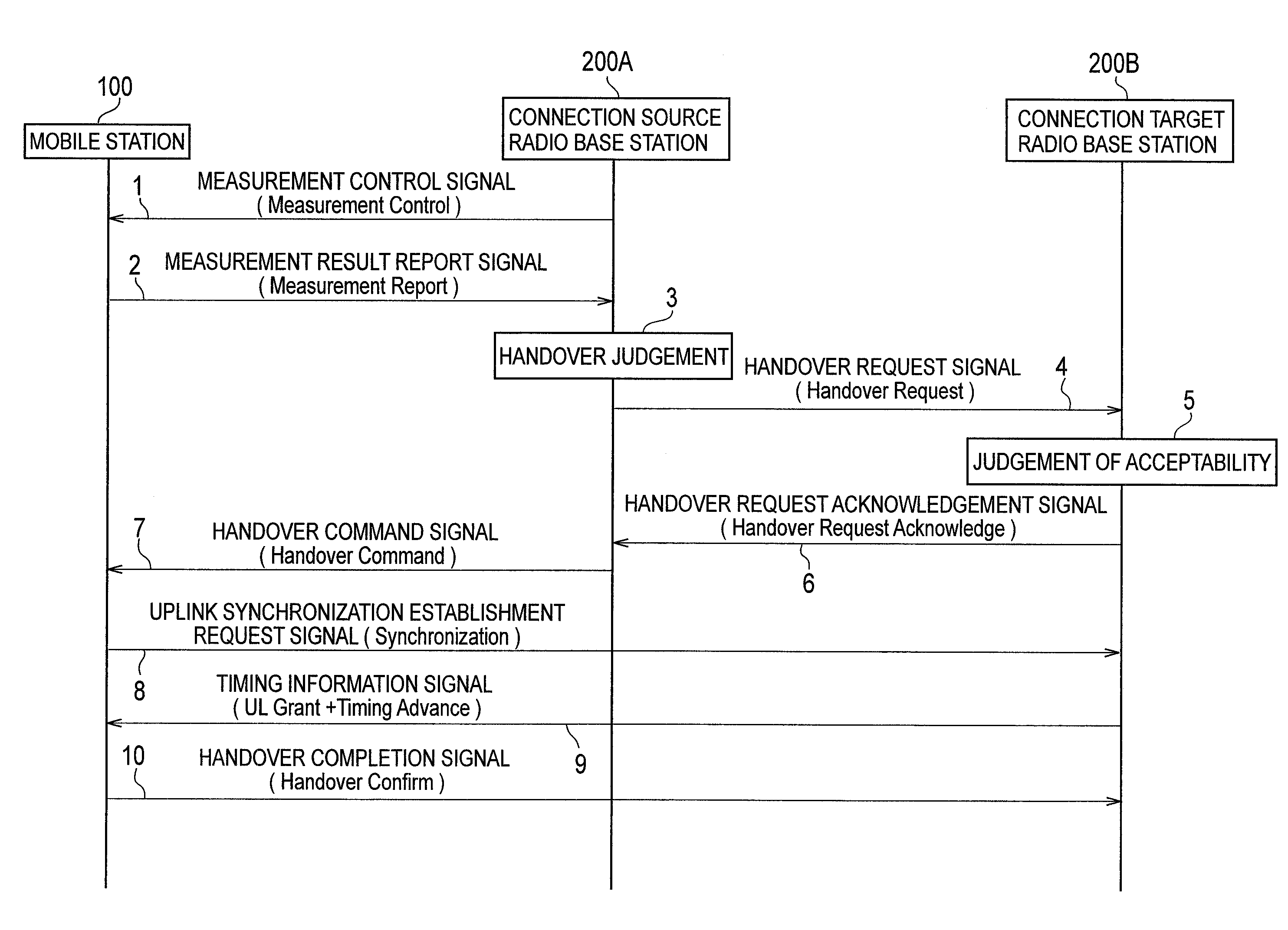
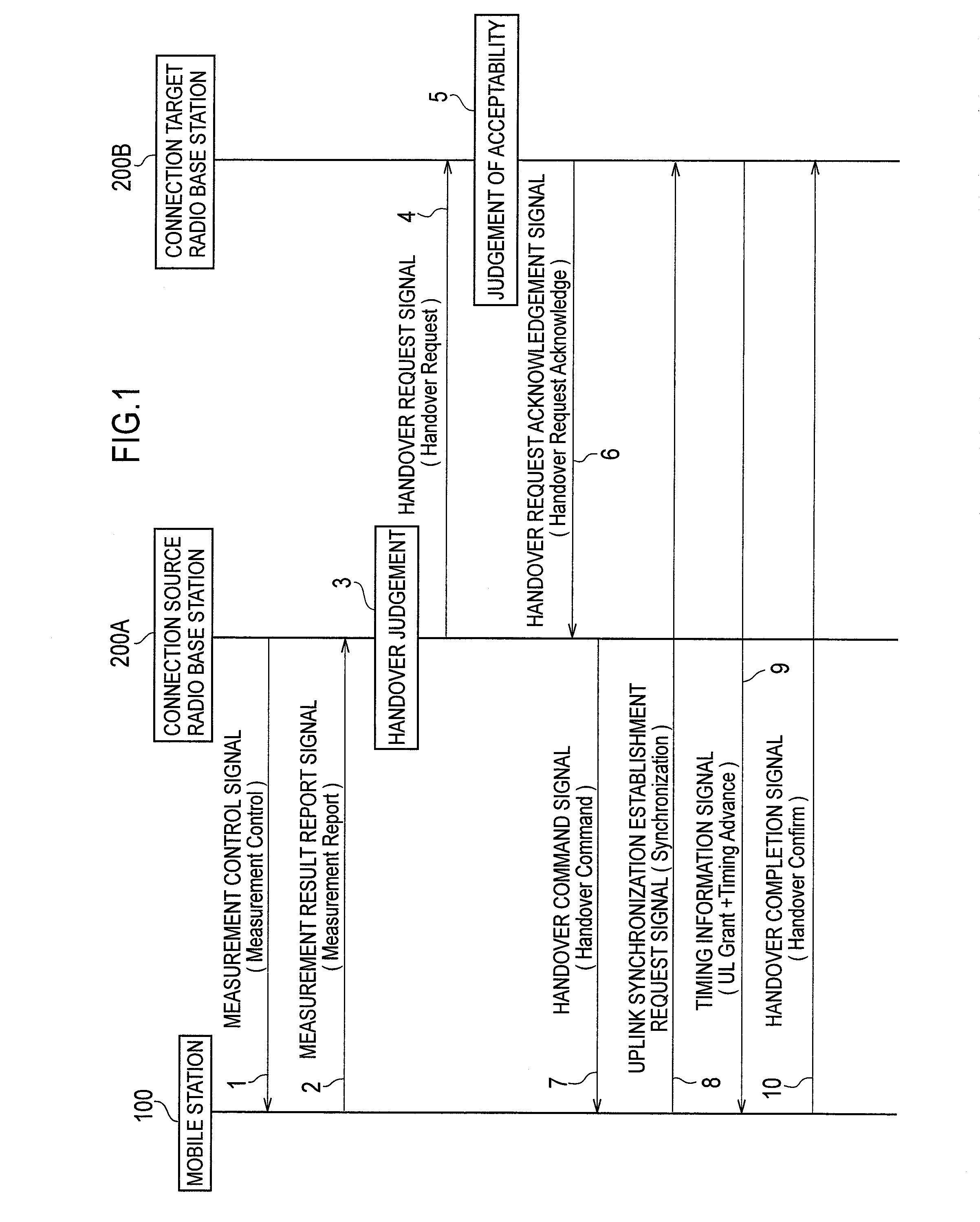
A radio base station (200A) according to the present invention includes: a radio related information retainer unit (206) configured to retain radio related information on connection between a mobile station (100) and the radio base station (200A); a handover request signal generator / transmitter unit (208) configured to transmit a handover request signal including the radio related information retained by the radio related information retainer unit (206) to a connection target radio base station (200B) ; and a handover command signal generator / transmitter unit (202) configured to transmit, to the mobile station, a handover command signal for notifying difference information between the radio related information retained by the radio related information retainer unit (206) and radio related information set by the connection target radio base station (200B) based on a handover request acknowledgment signal.

Description

TECHNICAL FIELD[0001]The present invention relates to a handover controlling method, a radio base station, and a mobile station.BACKGROUND ART[0002]A conventional mobile communication system allows a mobile station to continue communication while moving by performing handover control between the mobile station and a radio base station.[0003]To be more precise, when a mobile station in communication is about to move beyond the service area (cell) of a radio base station, the mobile station reports its radio quality to the radio base station to which the mobile station is being connected.[0004]The radio base station receives the radio quality and judges whether or not to cause the mobile station to switch to a cell in which the mobile station can communicate with better radio quality.[0005]If judging that the switching of a cell is necessary as a result of the above judgment, the radio base station instructs the mobile station to switch the cell (a handover).[0006]For example, in a mo...

Claims


Application Information

Patent Timeline
IPC IPC(8): H04W36/00
CPCH04W36/0055H04W36/08H04W36/0064H04W36/302H04W88/02
Inventor ISHII, MINAMINAKAMURA, TAKEHIRO
Owner NTT DOCOMO INC
Learn More