Stator of rotary electric motor and fuel pump

a technology of rotary electric motor and fuel pump, which is applied in the direction of piston pumps, positive displacement liquid engines, machines/engines, etc., can solve the problems of increasing costs

Active Publication Date: 2011-01-27
AISAN IND CO LTD
View PDF7 Cites 51 Cited by
  • Summary
  • Abstract
  • Description
  • Claims
  • Application Information

AI Technical Summary

Problems solved by technology

As a result, the number of components and the assembly man-hours are rather large, resulting in increase of cost.

Method used


Image

  • Stator of rotary electric motor and fuel pump
  • Stator of rotary electric motor and fuel pump
  • Stator of rotary electric motor and fuel pump

Examples


example 1

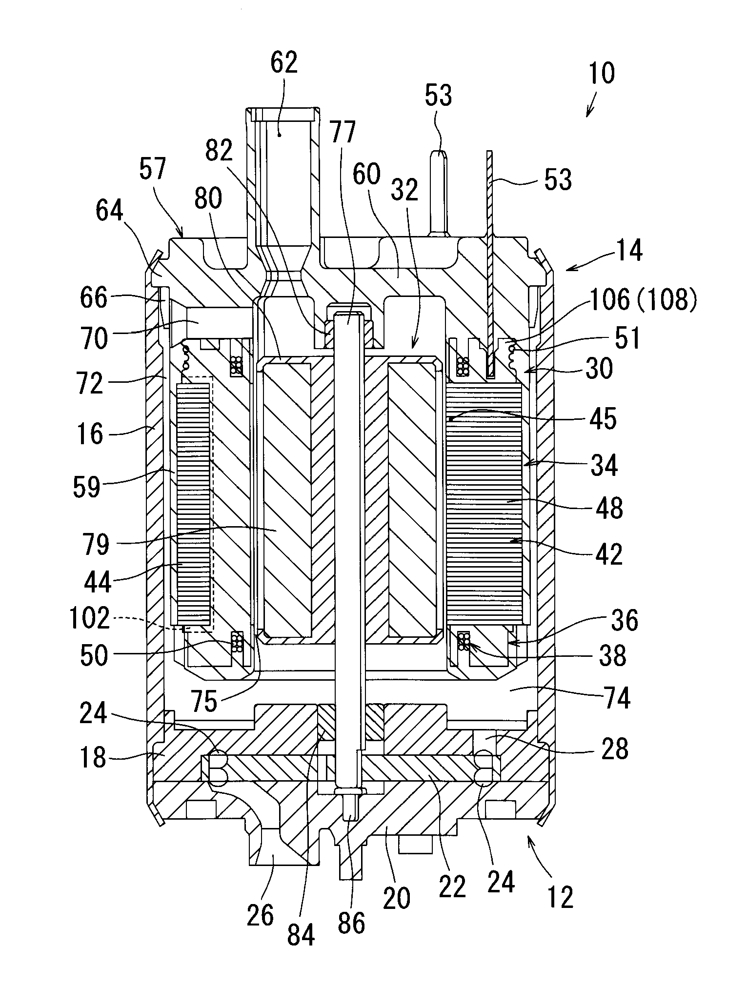
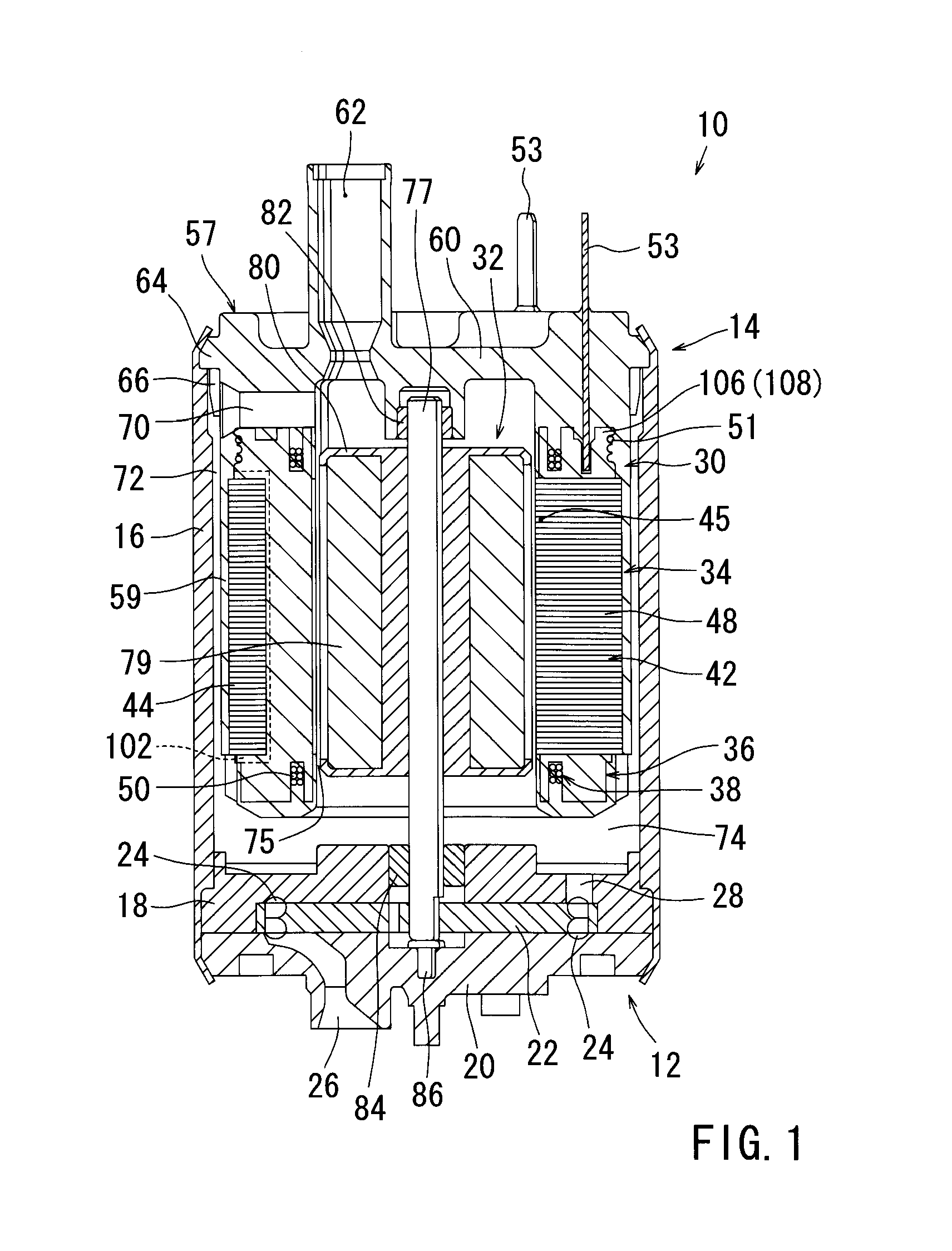
[0050]Example 1 will be described. For the sake of convenience in illustration, a fuel pump equipped with a stator of a rotary electric motor according to this example will be first described, and then a method of manufacturing the stator will be described. FIG. 1 is a sectional view as viewed from one side of a fuel pump, and FIG. 2 is a sectional view as viewed from an upper side of the same.

[0051]As shown in FIG. 1, a fuel pump 10 is an in-tank type fuel pump installed in a fuel tank of a vehicle, such as an automobile. The fuel pump 10 is equipped with a pump section 12 consisting of a Westco-type pump, and a motor section 14 driving the pump section 12. The pump section 12 and the motor section 14 are assembled within a housing 16. The housing 16 is formed of metal in a cylindrical tubular configuration. The pump section 12 is disposed within the lower portion of the housing 16, and the motor section 14 is disposed within the upper portion thereof. The motor section 14 serves a...

example 2

[0096]Example 2 will now be described. This example is applied to a stator for use in a 9-slot / 6-pole inner-rotor type three-phase brushless DC motor. FIG. 20 is a perspective view of a stator, FIG. 21 is a plan view of the same, and FIG. 22 is a sectional view as viewed from an upper sided of the same.

[0097]As shown in FIG. 20, a stator 150 is equipped with a core 152, bobbins 154, and coils 156. The core 152 is formed by arranging, in the circumferential direction and in an annular fashion, nine core segments 158 in total separated in the circumferential direction (See FIG. 22). The core segments 158 have yoke portions 160 arranged in an annular fashion, and teeth portions 162 protruding radially inwards from the yoke portions 160. Slots (which are not indicated by a reference numeral) are formed between the teeth portions 162 of the core segments 158 adjacent to each other in the circumferential direction. The core segments 158 are formed integrally through mutual crimping of pla...


PUM

PropertyMeasurementUnit
thicknessaaaaaaaaaa
thicknessaaaaaaaaaa
shapeaaaaaaaaaa

Abstract

A stator of a rotary electric motor has core segments. All or some of the core segments have terminal mounting members for mounting terminals to which coils are connected. The terminal mounting member and the bobbin for each of the core segments are molded by resin and integrated with the corresponding core segment.

Description

[0001]This application claims priority to Japanese patent application serial number 2009-172134, the contents of which are incorporated herein by reference.BACKGROUND OF THE INVENTION[0002]1. Field of the Invention[0003]The present invention relates to a stator of a rotary electric motor and a fuel pump.[0004]2. Description of the Related Art[0005]A known stator of a rotary electric motor is disclosed in Japanese Laid-Open Patent Publication No. 9-191588. The stator disclosed in this publication is equipped with a plurality of core segments arranged in an annular fashion, coils wound around the core segments through the intermediation of bobbins, and terminals (pins) which are provided on the bobbins and to which the coils are connected. The bobbins are formed by mounting a plurality of bobbin segments to the core segments.[0006]In order to assemble the stator disclosed in the above publication, it is necessary to perform a step of forming a plurality of bobbin segments, and a step ...

Claims


Application Information

Patent Timeline
Patent Type & Authority Applications(United States)
IPC IPC(8): F04B35/04H02K3/28H02K1/04H02K15/00
CPCH02K1/148H02K3/325Y10T29/49009H02K3/522H02K3/38
Inventor MATSUDA, TATSUHISAABE, FUTOSHIHANAI, KAZUMICHINAITO, HIROAKISUGIMOTO, ATSUSHIMIYAKE, FUSATOMO
Owner AISAN IND CO LTD
Why Eureka
Try Eureka