Wound Closing Device

a skin wound and applicator technology, applied in wound clamps, medical science, surgery, etc., can solve the problems of limited degree of control over the wound edge, unfavorable wound closure, and forceps not well suited to this task

Active Publication Date: 2011-01-27
BURKE KENNETH +1
View PDF25 Cites 54 Cited by
  • Summary
  • Abstract
  • Description
  • Claims
  • Application Information

AI Technical Summary

Benefits of technology

[0020]The most common method for bringing wound edges into alignment for application of tissue adhesive is the use of fingers. The user places gloved fingers of one hand on either side of the wound and squeezes the edges together. This method is limited by the amount of friction obtainable between the medical operator's gloved hand and the patient's skin. The medical operator's fingers must also apply downward pressure to either side of the wound in order to obtain friction, and this pressure can be painful for the patient. It is easily possible for the adhesive to flow to the medical operator's glove, sticking the glove to the patient's skin.
[0023]In each of the above present methods, it is important to recognize that while the tissue glue sets, the medical practitioner must maintain the wound edge alignment by holding the wound edges together. The present invention can eliminate this problem because the adhesive shoes allow the forceps to remain properly positioned on the skin surface even without the aid of the medical practitioner's hand holding them in place. The locking mechanism of the forceps holds the wound edges aligned. Thus the combination of the adhesive shoes and locking mechanism gives the medical practitioner the option to remove their hands from the forceps.

Problems solved by technology

The chief difficulty with using adhesives to close a wound is that the edges of the wound must be brought into alignment and held there as the liquid adhesive is applied.
However prior art forceps are not well suited to this task.
These mating surfaces give only a limited degree of control over the wound edges.
However it is not desireable for wound closure when using a tissue adhesive material in place of sutures.
Such limitations in the prior art therefore did not allow the use of two hands to stitch or apply the tissue glue.
Also In the prior art, if the patient moves then the forceps will move and the wound edges will not maintain registration.

Method used


Image

  • Wound Closing Device
  • Wound Closing Device
  • Wound Closing Device

Examples


Embodiment Construction

[0052]The present invention is designed for use within a medical treatment environment for the purpose of closing skin wounds in place of more traditional stitches.

MODE(S) FOR CARRYING OUT THE INVENTION

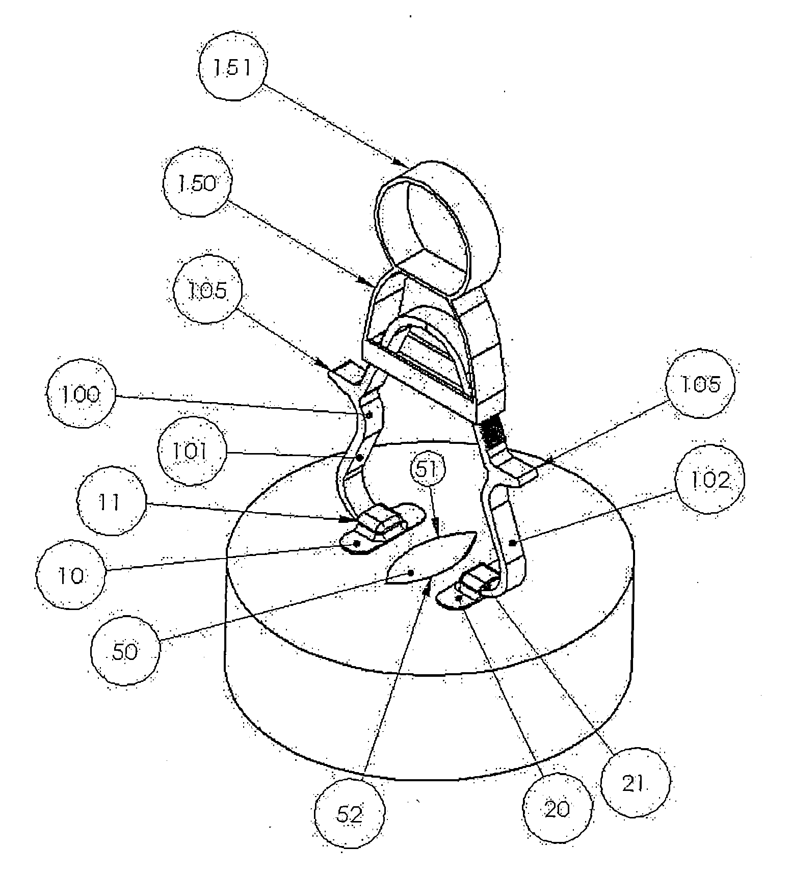
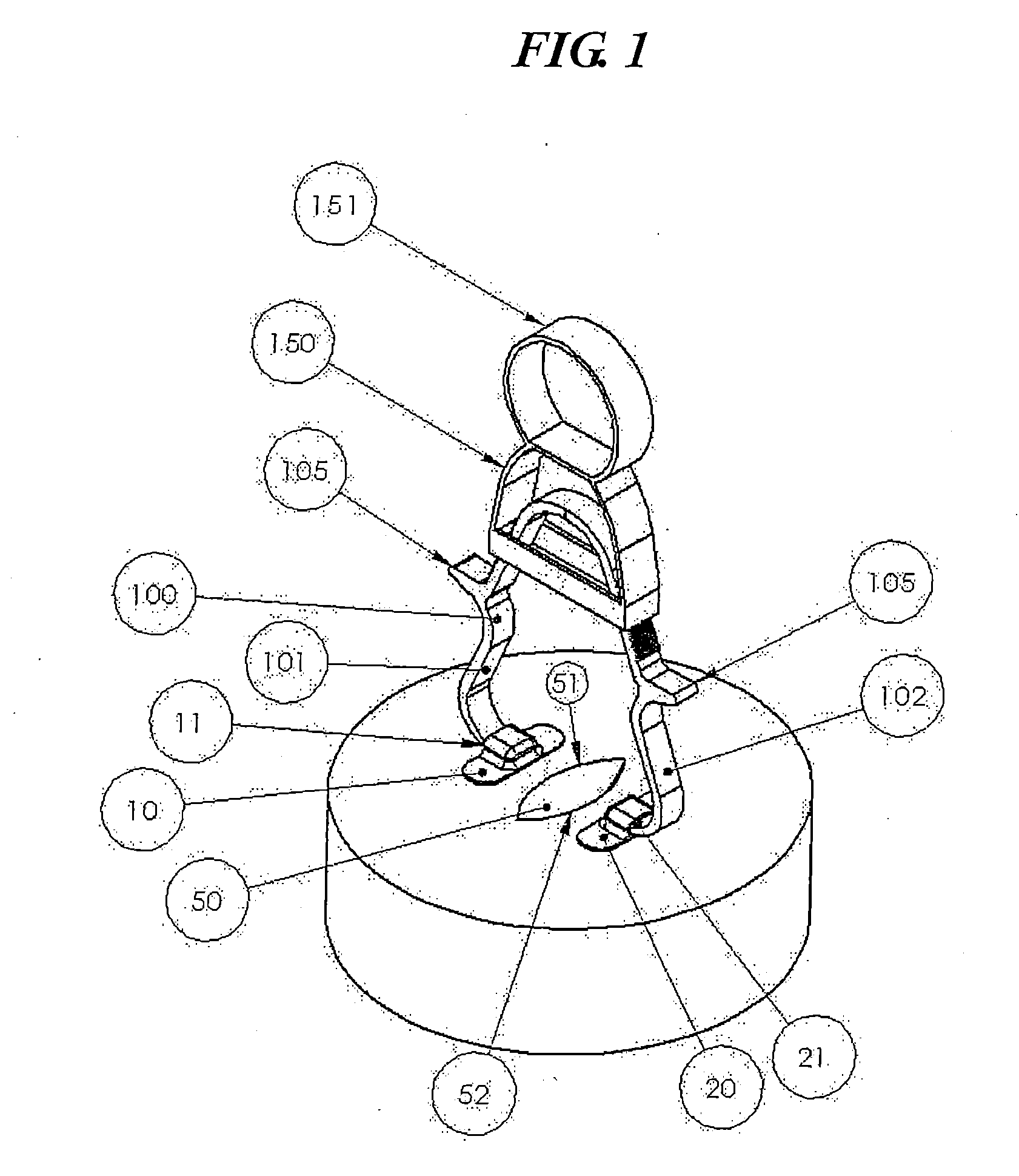
[0053]Refer first to FIG. 1, which shows a first illustrative embodiment of the present invention. A patient has an open wound 50 that a surgeon is working to close with a forceps device 100, such as tissue approximation forceps. A left adhesive shoe, such as a first bandage 10, is applied to the patient's skin adjacent to a first longitudinal edge 51 of wound 50. A right adhesive shoe, such as a second bandage 20, is applied to the patient's skin adjacent to a second opposing longitudinal edge 52 of wound 50. Next, the forceps legs 101 and 102 are slipped into the respective left and right shoes, such as open pocket portions 11 and 21 of the first and second bandages 10 and 20.

[0054]Other embodiments of the present invention use different configurations in place of adhesive shoes for...


PUM


Abstract

A wound (50) is closed using a first adhesive shoe (10) adhesively affixed adjacent to a first edge (51) of the wound, a second adhesive shoe (20) adhesively affixed adjacent to a second opposite edge (52) of the wound, a forceps device (100) comprising a first leg (101 ) adapted to couple with the first adhesive shoe and a second leg (102) adapted to couple with the second adhesive shoe; and a locking mechanism (150) adapted to draw the first and second forcep legs together and hold legs in the desired closed position after they are drawn together.

Description

BACKGROUND OF THE INVENTION[0001]1. Technical Field[0002]The present invention relates to an apparatus and method for closing a skin wound and more specifically to the art of using tissue glue in combination with tissue approximation forceps to glue wound edges together.[0003]2. Background Art[0004]In recent years, tissue adhesives such as the cyanoacrylates have become widely used for closing skin wounds, both those caused by trauma and those made as surgical incisions. In many cases, the use of tissue adhesives instead of skin sutures or staples allows wounds to be closed without the need for injecting local anesthetic into a wound, thereby expediting the procedure and sparing the patient the pain of an injection.[0005]When a wound is closed using sutures, the process of placing the sutures and tying the associated knots brings the wound edges into proper alignment at the same time that it closes the wound and secures that alignment. Thus it is not necessary to hold the wound edge...

Claims


Application Information

Patent Timeline
Patent Type & Authority Applications(United States)
IPC IPC(8): A61B17/03
CPCA61B17/085A61B17/083
Inventor BURKE, KENNETHBAIER, GARY
Owner BURKE KENNETH
Why Eureka
Try Eureka