Assisted-standing gear for use with dynamic-motion plates

a technology of dynamic motion and assisted standing, which is applied in the field of medical systems for the treatment of weak bone structures, can solve the problems of reducing the quality of life, and afflicting bones becoming more fragile and susceptible to breakage, so as to stimulate bone growth, reduce pain on patients, and bear the full weight of patients

a technology of dynamic motion and assisted standing, which is applied in the field of medical systems for the treatment of weak bone structures, can solve the problems of reducing the quality of life, and afflicting bones becoming more fragile and susceptible to breakage, so as to stimulate bone growth, reduce pain on patients, and bear the full weight of patients

US20070232965A1Inactive Publication Date: 2007-10-04AMERICAN MEDICAL INNOVATIONS LLC

Image

  • Assisted-standing gear for use with dynamic-motion plates
  • Assisted-standing gear for use with dynamic-motion plates
  • Assisted-standing gear for use with dynamic-motion plates

Examples


Embodiment Construction

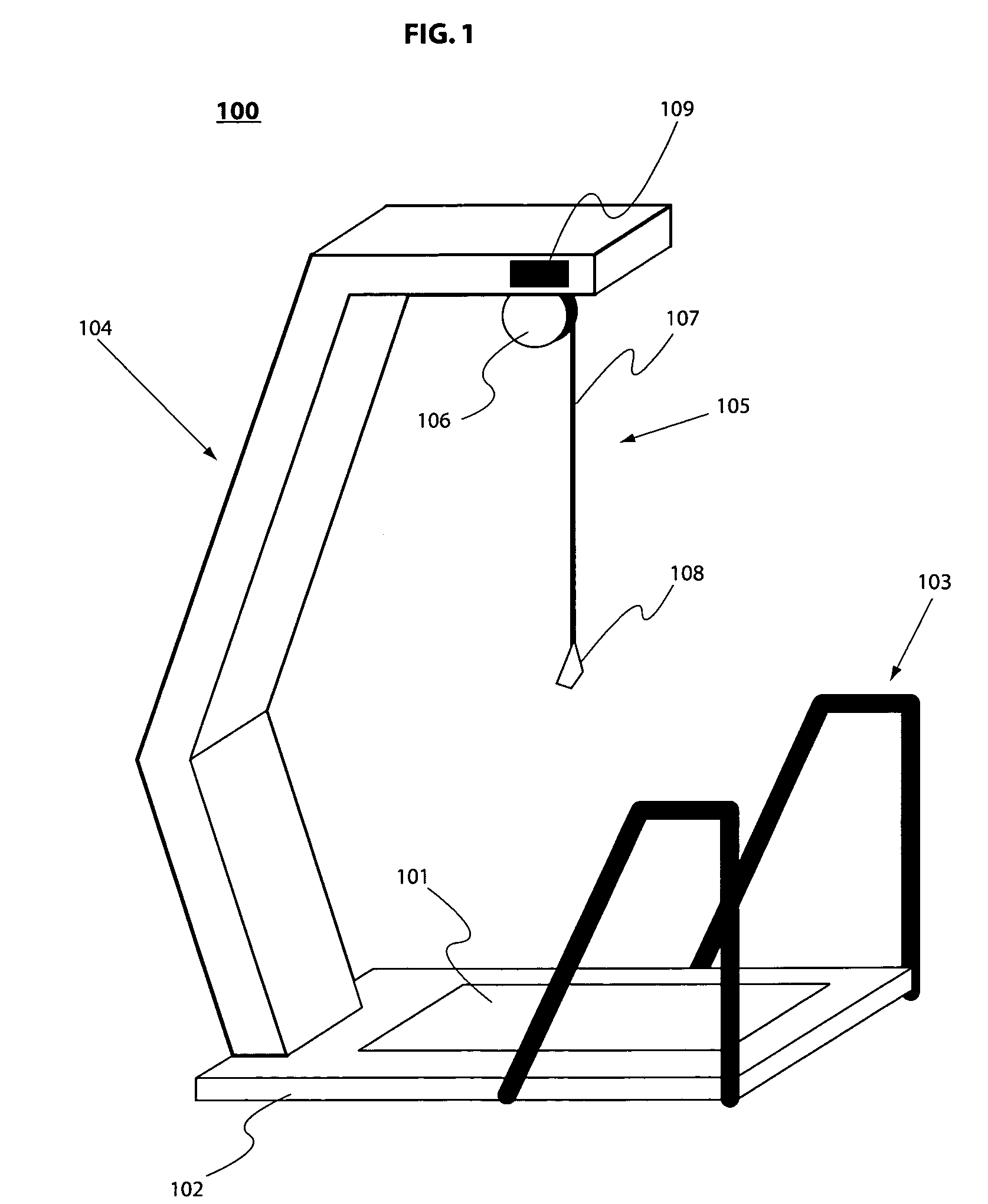
[0020]FIG. 1 illustrates a schematic view of a preferred embodiment of a system 100. The system 100 provides a dynamic motion plate 101 incorporated into a base 102. The base 102 is equipped with handrails 103 for providing a patient with lateral stabilizing support while the dynamic motion plate 101 is in operation.

[0021] Additionally, a cantilevered pillar 104 is mounted to the base 102. The cantilevered pillar 104 provides a support for a lifting system 105 consisting of a winch 106, cable 107 and a connector 108. The cantilevered pillar 104 and lifting system 105 should provide adequate support, strength and stability to lift patients that may not be able to fully support their weight for the duration of a treatment cycle due to overweight, injury or paralysis. The lifting system 105 may provide a means for varying the percentage of the patient's mass that is being supported by the cantilevered pillar 104. Collectively, the cantilever pillar 104 and the lifting system 105 are r...


PUM


Abstract

A medical treatment system is provided for the treatment of weakened bone structures caused by fractures, osteoporosis, or other bone related ailments using a dynamic motion plate. The medical treatment system utilizes a harness and lifting system to assist in supporting the weight of patients who are unable to remain in an upright posture on the dynamic motion plate for the duration of a treatment cycle.

Description

[0001] This application claims priority to a PCT application filed on May 5, 2005 and assigned International Application No. PCT / US2005 / 015628 which claims priority to a United States provisional patent application filed on May 24, 2004 and assigned U.S. Provisional Application Ser. No. 60 / 573,902; the entire contents of both applications are incorporated herein by reference.BACKGROUND [0002] 1. Technical Field [0003] The present disclosure, generally, relates to medical system for the treatment of weak bone structures and specifically for the treatment of weak bone structures using a dynamic motion plate in conjunction with assisted-standing gear directed at aiding a patient unable to maintain an upright posture for the duration of a treatment cycle. [0004] 2. Description of the Prior Art [0005] Weakened bone structure and improperly healed or slowly healing bone fractures may result in reduced quality of life. Quality of life may be improved for patients with bone fractures by ens...

Claims


Application Information

Patent Timeline
04 Oct 2007
Publication
US20070232965A1
IPC
A61H1/02; A63B26/00
CPC
A61H1/005; A61H1/006; A61H3/008; A61H2203/0406; A61H2201/1215; A61H2201/1616; A61H2201/5061; A61H2201/1623
Inventors
TALISH, ROGER J.