
Aromatic nebulizing diffuser

a diffuser and nebulizing technology, applied in the direction of atomized substances, movable spraying apparatus, disinfection, etc., can solve the problems of lowering the generating performance of fin mist, unable to simulate the natural visual effect of flying mist, and taking a lot of time and labor to practice cleaning work, so as to achieve efficient production of aromatic fluid fine mist, prevent leakage of storage aromatic fluid, and avoid danger

Inactive Publication Date: 2011-02-03
HSIAO MING JEN
View PDF7 Cites 40 Cited by
  • Summary
  • Abstract
  • Description
  • Claims
  • Application Information

AI Technical Summary

Benefits of technology

[0010]It is another object of the present invention to provide an aromatic nebulizing diffuser, which prohibits leakage of the storage aromatic fluid upon accidental falling, avoiding danger.
[0011]It is still another object of the present invention to provide an aromatic nebulizing diffuser, which produces sound and lighting effects while generating a fine mist of aromatic fluid droplets.
[0012]It is still another object of the present invention to provide an aromatic nebulizing diffuser, which generates a fine mist of aromatic fluid droplets efficiently.

Problems solved by technology

They cannot simulate the natural visual effect of a flying mist caused by the impact of a waterfall.
Further, regular aromatic nebulizing diffusers commonly use screws to affix component parts together, complicating mounting and dismounting procedures.
It takes much time and labor to practice a cleaning work.
This gradually reducing diameter design tends to cause the generated fine mist to be condensed into water drops, lowering the fin mist generating performance.
Further, when a thermal type, electronic type or ultrasonic type aromatic diffuser falls to the floor accidentally, the contained essential oil may leak out, causing risks and damages.

Method used


Image

  • Aromatic nebulizing diffuser
  • Aromatic nebulizing diffuser
  • Aromatic nebulizing diffuser

Examples


Embodiment Construction

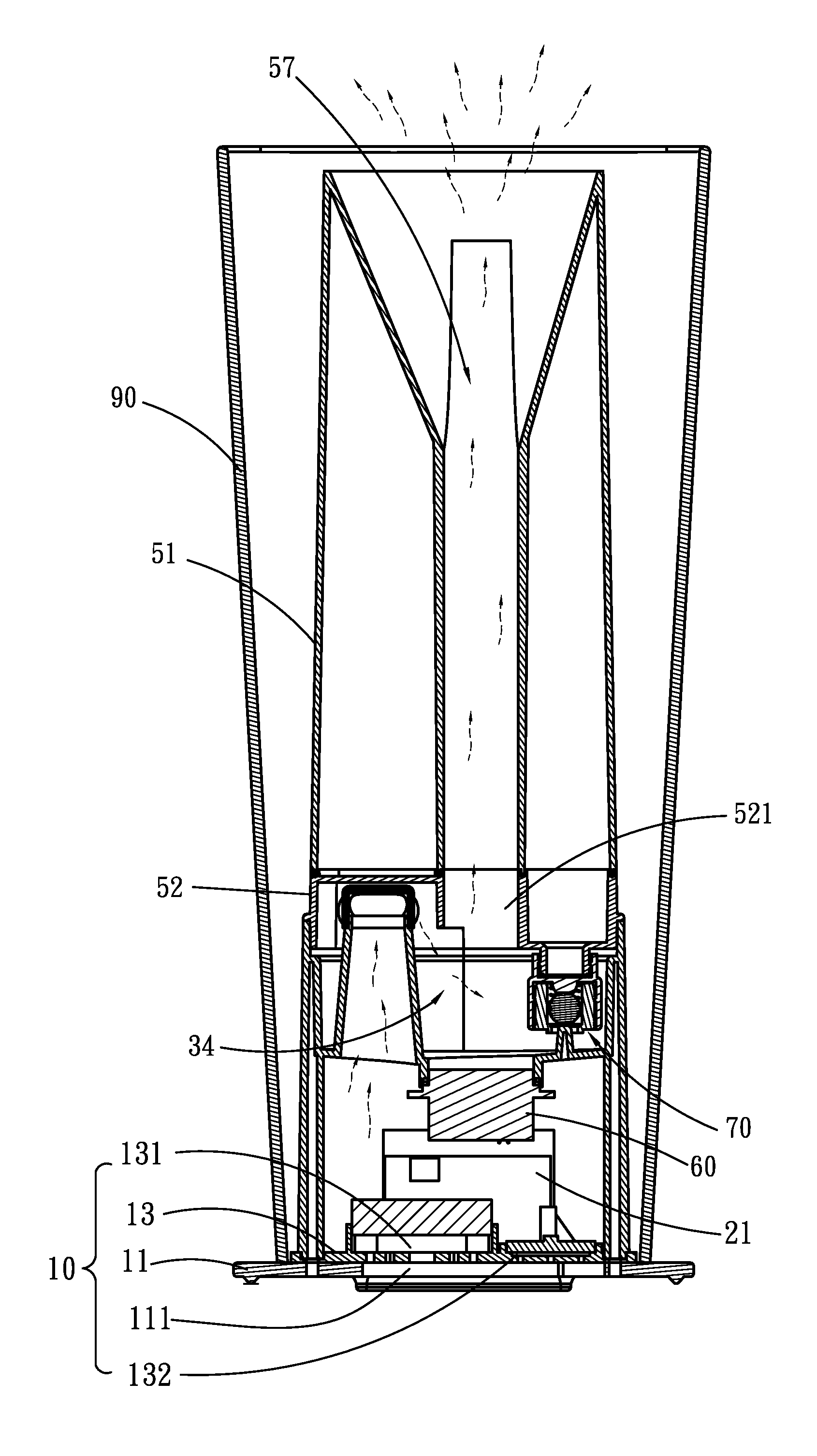
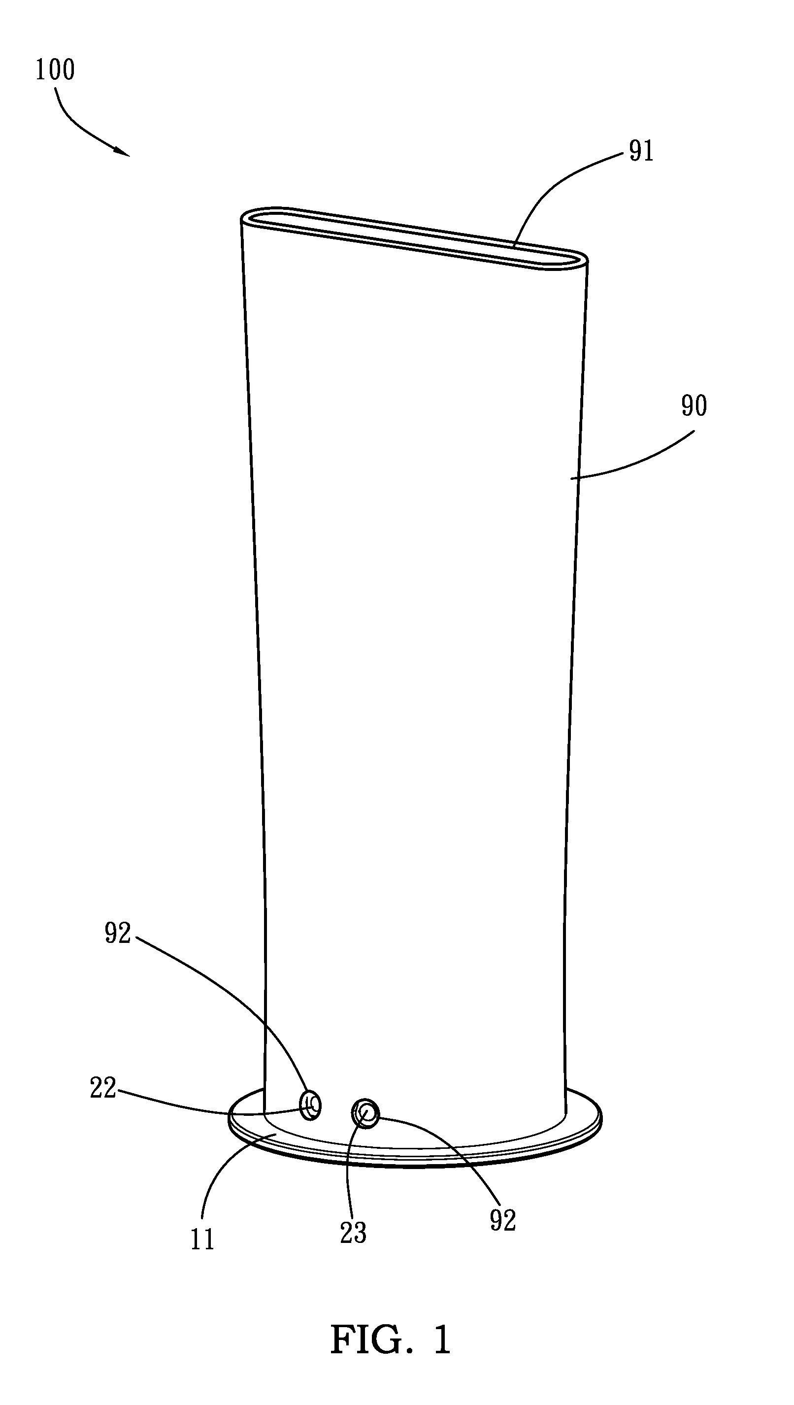
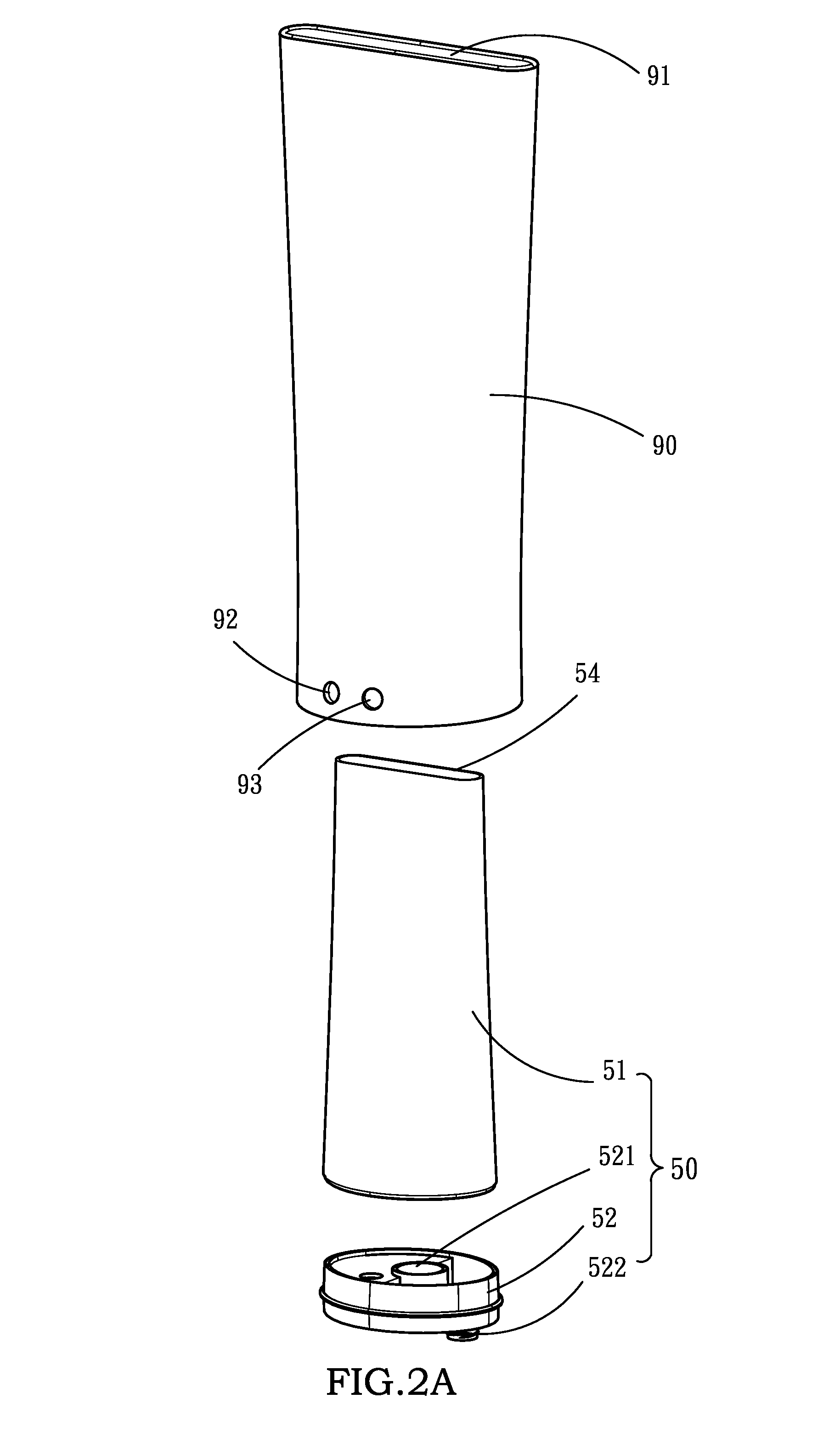
[0023]Referring to FIGS. 1, 2A, 2B and 3, an aromatic nebulizing diffuser 100 in accordance with the present invention is shown comprising:

[0024]a base panel 10;

[0025]an electronic control unit 20 mounted on the base panel 10;

[0026]an electric fan 40 mounted on the base panel 10 and electrically connected to the electric control unit 20;

[0027]a holder 30, which has a transverse partition board 31 that has a center opening 36 and divides the holder 30 into an upper part that defines an oscillation chamber 34 and a lower part that defines a cover 32, and an air passage 56 formed of an open-ended duct and set in air communication between the space inside the cover 32 and the oscillation chamber 34 to provide a path for delivering air currents caused by the electric fan 40;

[0028]a fluid container 50, which is mounted in the holder 30, comprising a container body 51, a container base 52 fastened to the bottom side of the container body 51 and defining with the container body 51 a fluid s...


PUM


Abstract

A high-safety, high-performance aromatic nebulizing diffuser capable of producing sound and lighting effects is disclosed to include a base panel, an electronic control unit, a speaker, an electric fan, a fluid container, an ultrasonic oscillator, a fluid intake control device set in between the oscillation chamber and the fluid container, a dip tube in communication between the oscillation chamber and the fluid container and changeable between an open status and a close status to control the fluid intake control device in closing / opening the passage between the oscillation chamber and the fluid container, an outer housing, a holder defining an oscillation chamber at the top and a cover at the bottom, an air passage in air communication between the oscillation chamber and the cover for the passing of currents of air caused by the electric fan, an exhaust passage for guiding a generated fine mist of aromatic fluid droplets out of the oscillation chamber into the atmosphere.

Description

BACKGROUND OF THE INVENTION[0001]1. Field of the Invention[0002]The present invention relates to an aromatic nebulizing diffuser and more particularly, to such an easily detachable nebulizing diffuser of high level of safety that provides sound and lighting effects.[0003]2. Description of the Related Art[0004]A known aromatic nebulizing diffuser or essential oil diffuser uses an ultrasonic oscillator to generate a high ultrasonic energy for causing atomization of an essential oil for application. Separation of electric charges in falling rain, caused by breaking up of the water droplets, the drops becoming positively charged and the air negatively charged. This separation of electric charges accompanying the aerodynamic breakup of water drops is known as spray electrification, the waterfall effect or Lenard effect. Conventional aromatic nebulizing diffusers simply produce an upwardly flying mist of aromatic gas. They cannot simulate the natural visual effect of a flying mist caused ...

Claims


Application Information

Patent Timeline
Patent Type & Authority Applications(United States)
IPC IPC(8): B05B3/04B05B17/00
CPCB05B7/0075B05B17/0615B05B17/0669B05B17/0676B05B7/0012A61L2209/111A61L2209/12A61L2209/13A61L2209/132A61L9/14B05B17/06
Inventor JORGENSEN, CARSTEN
Owner HSIAO MING JEN
Learn More