

Illumination Device For A Microscope
a technology of microscope and illumination device, which is applied in the field of illumination device for microscope, can solve the problems of affecting the focusing and manipulation of objects, the dome cannot be adapted to the different working distances, and the user is injured, so as to avoid injury and damage to the reflector or the microscope, and the user is easy to operate. , the effect of avoiding injury and damag
- Summary
- Abstract
- Description
- Claims
- Application Information
AI Technical Summary
Benefits of technology
Problems solved by technology
Method used
Image

Examples
embodiment 200
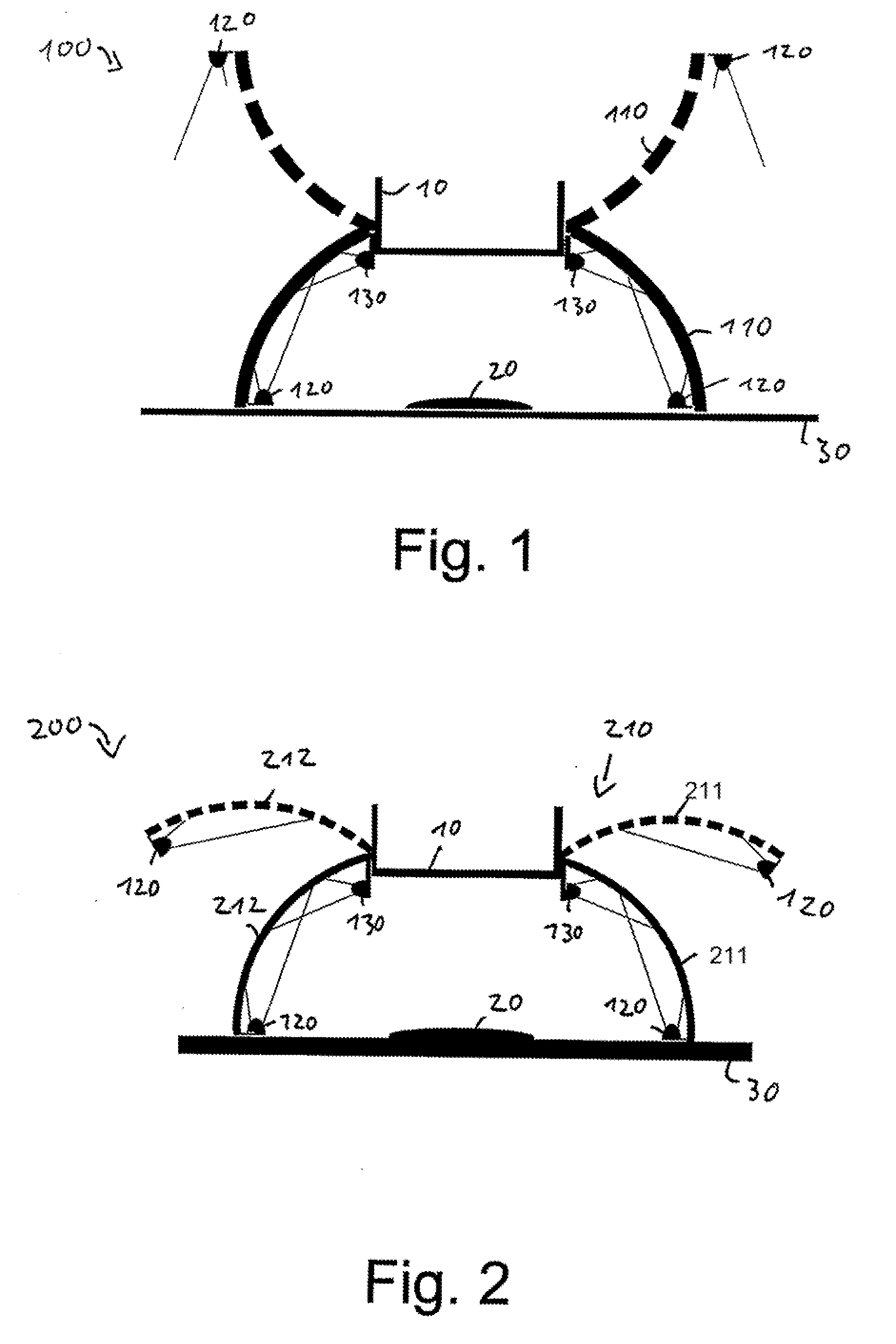
[0035]FIG. 2 shows a further embodiment 200, in which hemispherical reflector 210 is formed of a plurality of flexible elements 211, 212. The flexible elements are shaped as surface elements of a hemisphere, in particular in the shape of a spherical quadrangle. The transformation is accomplished by folding the individual segments 211, 212 back. A top view of reflector 210 is shown in FIG. 10.
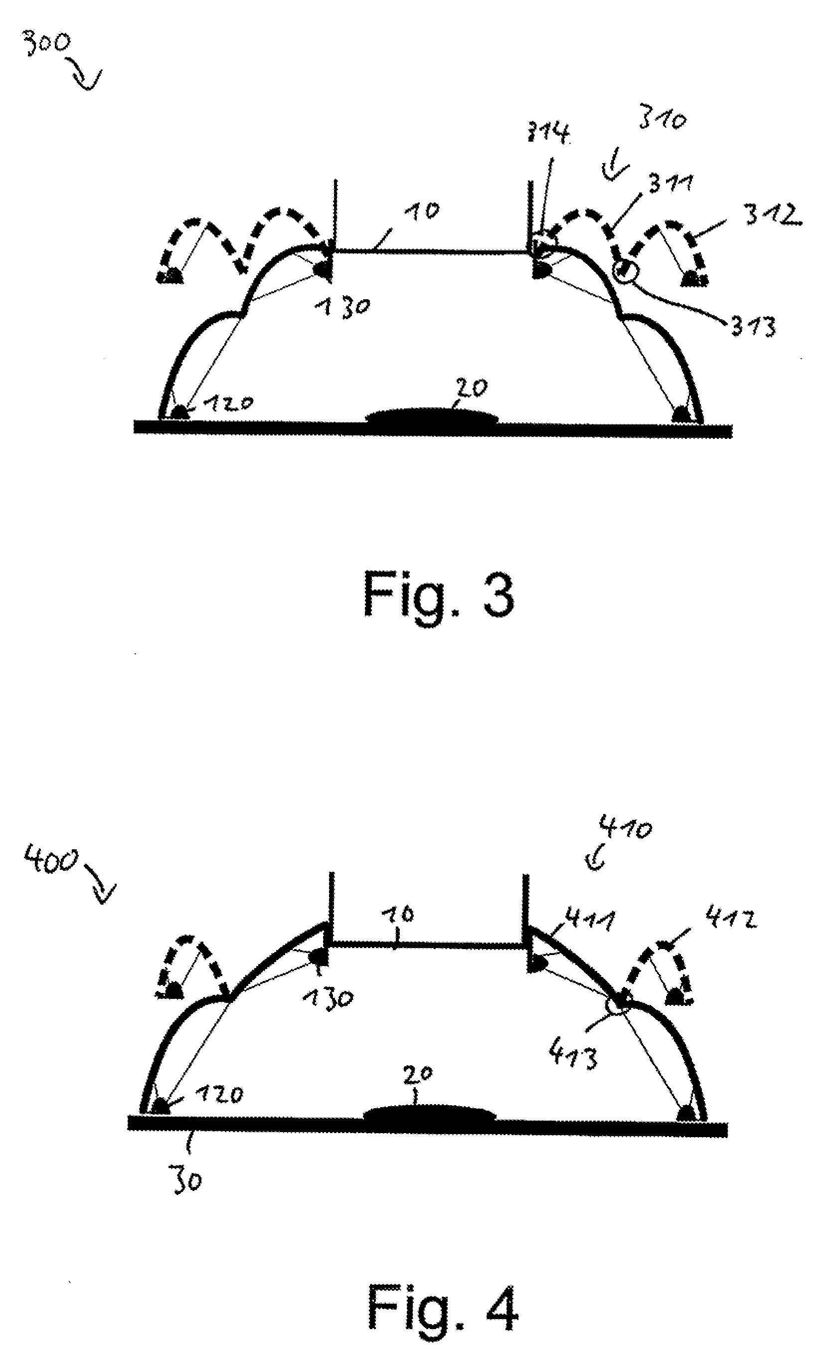
[0036]FIGS. 3 and 4 show two embodiments of an illumination device 300, 400 according to the present invention, whose reflectors 310 and 410 are substantially bell-shaped. Reflectors 310 and 410 each have a first portion 311 or 411, and a second portion 312 or 412, which are linked by a joint 313 or 413, respectively. Portions 311, 312 and 412 are flexible, whereas portion 411 is rigid. Illumination device 300 further has a joint 314 connecting reflector 310 to the mounting means, for example a clamping ring, on objective 10.
embodiment 300
[0037]When in its first, closed spatial form, embodiment 300 of FIG. 3 produces a diffuse illumination of object 20. The second, open spatial form makes it possible to provide the greatest possible access to object 20 without the need to change the distance between the object and the objective for this purpose. Moreover, when in the second, open spatial form, illumination device 300 occupies little space, which is advantageous, in particular, for storage purposes.
[0038]FIG. 4 shows an illumination device 400 which, in the first, closed spatial form, corresponds to illumination device 300 according to FIG. 3. However, when in the second, open spatial form, illumination device 400 differs from illumination device 300. Because portion 411 is rigid, a diffuse illumination of object 20 is maintained in the second spatial form, thus enabling simultaneous observation and manipulation of the object.
embodiment 500
[0039]In FIG. 5, a fifth preferred embodiment of an illumination device of the present invention is shown in a first, second, and third spatial form in a schematic cross-sectional view and denoted as a whole by 500. The first spatial form is indicated by a solid line, the second spatial form is represented by a short-dashed line, and the third spatial form is indicated by a long-dashed line. Reflector 510 of illumination device 500 is substantially entirely flexible and has a very high degree of elasticity. This allows for attachment to objectives 10, 11, and 12 having different working distances, and yet allows object 20 to be substantially completely screened from the environment. In the case of embodiment 500 shown, the first, second and third positions are all closed positions. An open position can be attained, for example, by the user lifting the lower edge of reflector 510.
PUM
 Abstract
Description
Claims
Application Information