Ethernet Switch and System

Inactive Publication Date: 2011-02-03
HE ZIQIANG
View PDF12 Cites 55 Cited by
  • Summary
  • Abstract
  • Description
  • Claims
  • Application Information

AI Technical Summary

Benefits of technology

[0014]FIG. 3 is a more detailed circuit diagram showing a dual-transformer module operati

Problems solved by technology

However, an unmanaged Ethernet switch that is available today on the market is not capable of providing such traffic visibility or port mirroring function.
Such a manual configuration process obviously adds complexity or difficulty in u

Method used


Image

  • Ethernet Switch and System
  • Ethernet Switch and System
  • Ethernet Switch and System

Examples


Embodiment Construction

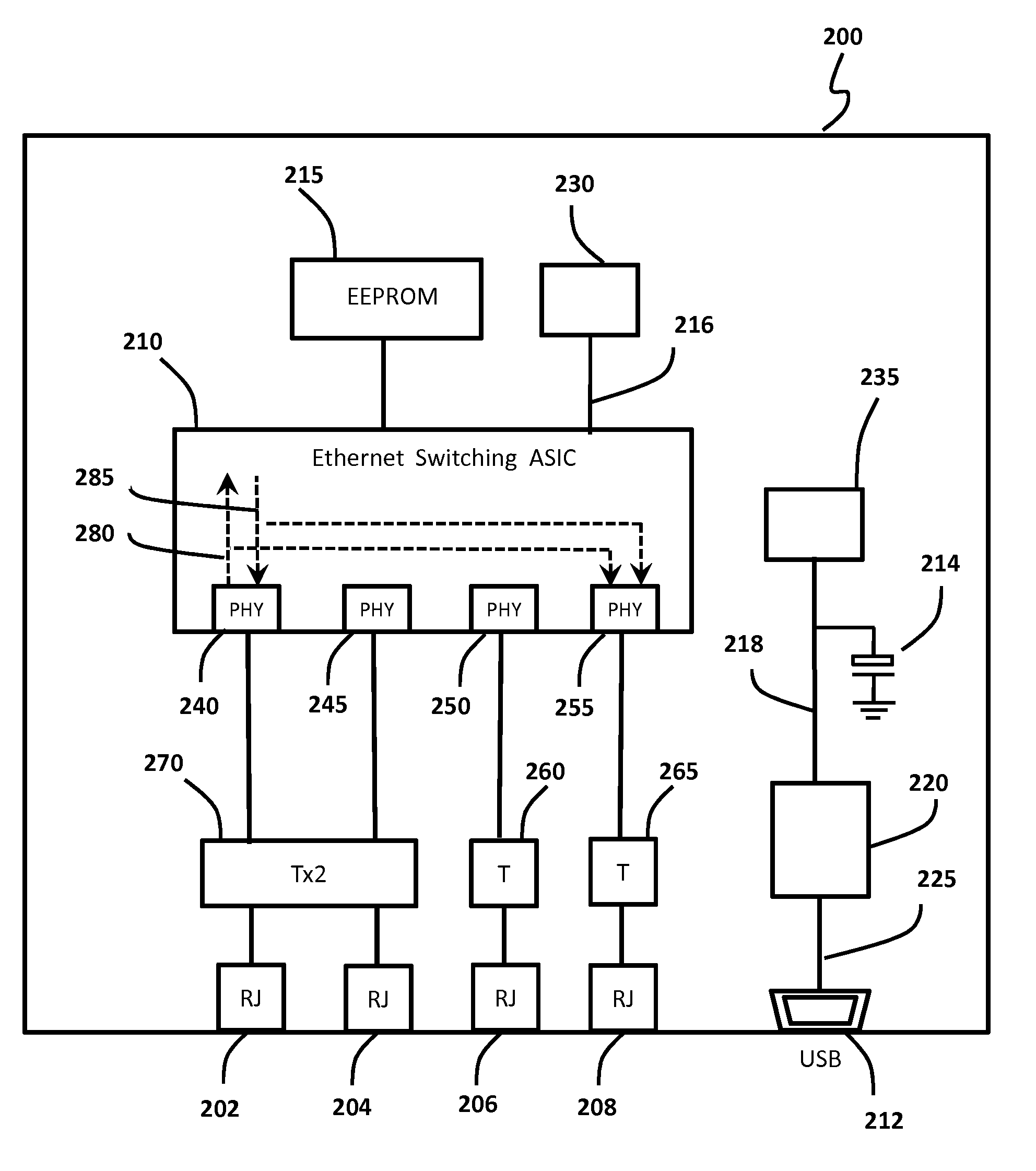
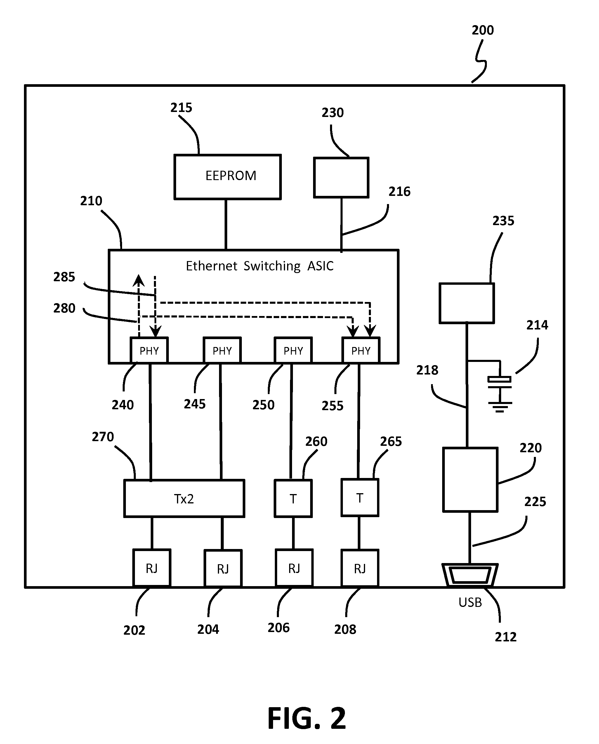
[0016]FIG. 2 is a block diagram of an Ethernet switch 200 for providing port-mirroring functionality without manual configuration by a user in accordance with an embodiment of the invention. The Ethernet switch 200 is implemented with an Ethernet switching Application Specific Integrated Circuit (ASIC) 210 which is integrated with multiple Ethernet physical layer transceivers (PHYs) that are referred to as PHY ports 240, 245, 250 and 250 hereinafter. Specifically, a single-chip 5-Port 10 / 100 / 1000 Switch Controller, RTL8366SB, from Realtek Semiconductor Corp., can be used as the Ethernet switching ASIC 210. The Ethernet switching ASIC 210 operates in such a way that it forwards a data packet received on any PHY port 240, 245, 250 or 250 to another one or more PHY ports based on the destination MAC address of the received data packet. A received packet can be forwarded to more than one PHY ports if the data packet is a broadcast packet according to the Ethernet IEEE 802.3 standard.

[00...


PUM


Abstract

An Ethernet switch includes a plurality of network ports, wherein visibility of data packets traffic is configured by loading port-mirroring related configuration data from a configuration memory device into the Ethernet switch upon power-on reset. As a result, no manual configuration by a user is required, and the hardware cost of the Ethernet switch is reduced. The Ethernet switch is further configured to enable pass-through of Power over Ethernet (PoE) inline power between two selected network ports. A USB connector is further included and adapted for the Ethernet switch to receive input power from a USB port of a USB host device and for the Ethernet switch to send and receive data packets to and from the USB host device.

Description

CROSS-REFERENCE TO RELATED APPLICATIONS[0001]This application claims priority from Provisional Application No. 61 / 230,749, filed Aug. 3, 2009, and Provisional Application No. 61 / 248,436, filed Oct. 3, 2009.FIELD OF THE INVENTION[0002]This invention relates generally to communication networks. More particularly, this invention is related to a new and improved Ethernet switch capable of providing data packet traffic visibility.BACKGROUND OF THE INVENTION[0003]Ethernet switches are networking apparatus used in a Local Area Network (LAN) to connect computers and other related network devices for facilitating data packet communications among such connected computers and other related network devices.[0004]FIG. 1 illustrates a typical LAN 100. A first Ethernet switch 105 includes a set of network ports, each network port is connectable to a network device such as a printer 140, a server 145, a Voice over IP Private Branch Exchange (VoIP PBX) 150 or a wireless access point (AP) 155; a seco...

Claims


Application Information

Patent Timeline
IPC IPC(8): H04L12/56
CPCH04L49/109H04L49/351
Inventor HE, ZIQIANG
Owner HE ZIQIANG
Why Eureka
Try Eureka