

Tamper-proof nut or bolt head security cover
- Summary
- Abstract
- Description
- Claims
- Application Information
AI Technical Summary
Benefits of technology
Problems solved by technology
Method used
Image

Examples
Embodiment Construction
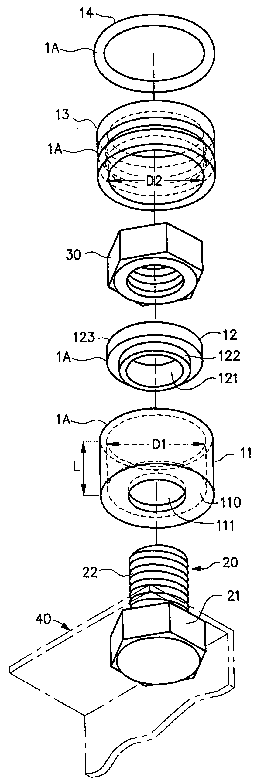
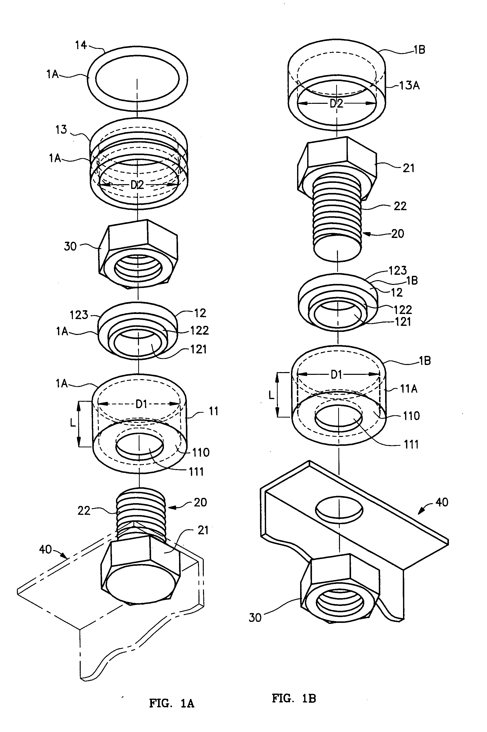
[0062]Two embodiments of the security cover of the present invention deployed to protect a nut that is threaded to a shaft, and deployed to protect the head of a bolt (holding, by way of example, a solar panel) are respectively shown in exploded perspective view in FIGS. 1a and 1b.
[0063]FIGS. 1a and 1b respectively show a first, four-component-part and a second, three-component-part, embodiment of a tamper-proof security cover 1 in accordance with the present invention. The four component parts of the first embodiment of FIG. 1a are the walled hollow cylinder, or housing, 11; the step washer 12; the cap 13; and the ring 14. The three component parts of the second embodiment of FIG. 1b are the walled hollow cylinder, or housing, 11A; the step washer 12; and the cap 13A, the ring 14 being omitted.
[0064]The view of FIG. 1a shows a nut 30 threading a threaded shaft 22 of a bolt 20, and the view of FIG. 1b equivalently shows the head 21 of the bolt 20, as the bolt 20 and nut 30 become t...
PUM
 Abstract
Description
Claims
Application Information